[help] Designing am transmitter
I have some question about this circuit
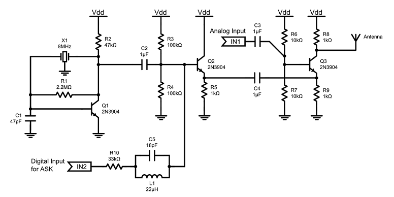
Can anyone explain how to work this transmitter (specially Q3,work as mixer)?
Here is what I see:
1.) There is a 8Mhz crystal that is oscillating into Q1, effectively turning it off and on
2.) C2 is used to filter the DC from the oscillator
3.) DC biased voltage divider mixed with the ASK reasonator that feeds into Q2
4.) Resonating signal is filtered by C4
5.) analong input controls the Q3 transistor
6.) The analog signal is mixed into the reasonating carrier signal
7.) Resonating carrier signal is amplitude controlled with mixed analog input signal
more questions:
Where does feedback occur? with xtal or 2.2m R?
And is this R1 resistor necassary? Can i remove it from circuit?
R1 provides the base bias for Q1 so yes it is kind of important.
The feedback is via the crystal which wil be run at its series resonance.
This thing is not a very good transmitter, it will have poor modulation linearity and needs an output filter to ensure the RF harmonics are sufficiently attenuated, the common base 'power' (maybe 10dBm or so ?) stage is kind of interesting howevr.
I wonder to what extent those overly large 1uF coupling caps contriute to modulation by allowing audio input to change the bias point of the previous stage (I am not curious enough to spice it)?
Regards, Dan.
First of all ty for helps.
If i add output filter, will this circuit works properly ? And what is the output filter, how can i make it ?
The best thing to do is to replace R8 with a tuned circuit. If your aerial is 300/ 4 X F m. long then its a good aerial ( 9m), if the aerial is shorter then it needs an inductor in series with it to tune it and the aerial should be connected to a tap on the new tuned circuit (~ 10 % away from the Vdd end). So now you have two additional tuned circuits, both of which reduce the harmonic output and increase the output.
Frank
Thank you man, i will search these. Then i may ask some questions again :)
I have two important questions.
1- How can i determine C and L value for tuned circuit?
2- I dont understand that which part in this circuit work as mixer and how? When i try to find mixer circuit i find more complex circuit such as below
http://obrazki.elektroda.pl/1619528600_1405014227.jpg
p.s: I don't need powerfull transmitter. When i run this transmitter circuit i want to hear signals smoothly in 2-3 meter area
i found like that for mixer
http://www.st-andrews.ac.uk/~www_pa/...rt9/page1.html
It is obviously this circuit can be used for mixer. (i understand from equations.)
How can i explain that Q3 works as mixer? Can you tell me it with formulas and equations?
Ty again
Cck
Can i get it from
or
with taylor series,,
Last question guys,
How can i model xtal in spice for simulation?