Tuning input and output impedance without effect on each other
I am designing a LNA with S-parameters of a transistor. After I have designed the circuit I have to adjust its input and output matching, but they affect on each other so badly! I mean I adjust input matching at 75 Ohm, after adjusting output matching at 75 Ohm, input matching changes so much and I cannot see output matching at 75 Ohm!
What should I do? Is there any way to isolate them?
hi there
show us your circuit.
Its a very difficult to give good advice without seeing your setup
cheers
Dave
From microwaves101:
So basically it's all dependent on the S21 and S12 of your LNA device.
Use "simultaneously conjugate matching" technique if you play in a narrowband.You can find some information about it in textbooks.
Bu I guess you design a wideband LNA and this technique is not valid in that case.Instead, check your feedback circuits ( series and parallel ) to stabilize inout and output impedances.Since S12==0 , you will see similar problems and it's not easy to overcome that..
davenn,
Here is my circuit:

mtwieg ,
Ok, but what should I do to fix it? I think there would be a way to match two sides in true way.
BigBoss,
I am working at 0.6 GHz(center frequency) and 0.5 GHz to 0.7 GHz (cut-off frequency).
I have used Impedance Matching and Smart Component in ADS because I though that it would solve my problem, but it didn't. I mean I adjusted input and output impedance and let ADS to match my input and output networks automatically. Does it have a better accuracy?
if you optimize your circuit for S12 as small as possible, then the output will be pretty decoupled from the input tuning. If you use 2 stages of amplification, then same. Otherwise, it is something you just have to deal with

I have designed for both input and output matching circuit by optimization method.Looks good but a better combination can probably be found

I did optimization too. My figures are so much better now, but they are not great.
I advise engineers who wants to know how should use optimization to match use this document(It helped me so much):
http://www.utdallas.edu/~rmh072000/S...les/5B_lab.pdf
Why ? Take and use my values , the frequency response is quite good.Reflections are also pretty good.
What are you looking for out of that?/
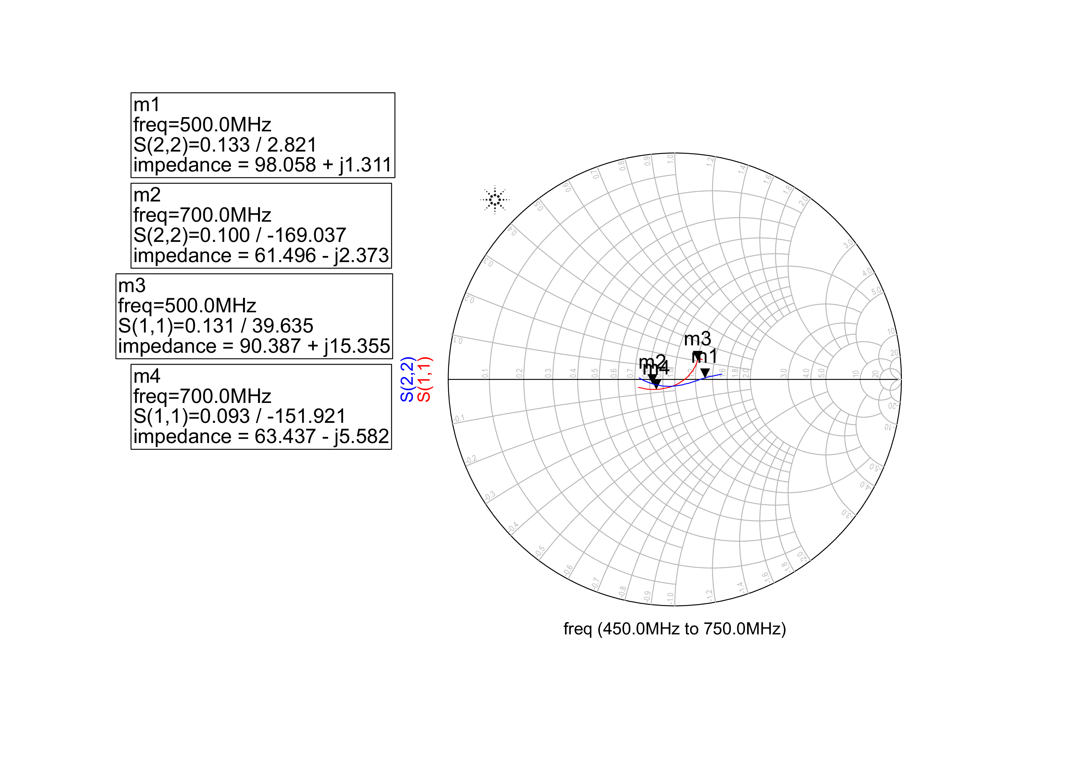
Here is my simulation results:
S22 is fine, but s11 is not fine.


The point is that I can refine S11 by adding a more complicated Matching Network and after that I should optimize the network, but It would be so many capacitors and Inductors and because I want to fabricate the circuit, as I add more components It would be more parasitic affects specially between pins of the components (SMD) and the board. So, I prefer to have lower S11, but more simple Network.
Why don't you use my values ? Input and Output impedances are almost 75 Ohm.You don't have to use more complex circuit, just simple L-L-C matching circuit.
You don't want to use the feedback ?
I have plotted S11 and S22, don't confuse Zin or Zout.
Zin and Zout are not used for RF matching circuits they are practically useless, instead S-Parameters are used to estimate how much power will be reflected by the circuit.
Dear BigBoss,
First of all, I have used you circuit and your values, but its maimum and its minimum are far from each other(MaxZin_MaxZout).
Secondly, I have used your circuit and an optimization on your circuit, but it does not have a smooth figure. I mean its maximum and its minimum are far from each other. Look at it here:


Thirdly, I use Zin and Zout simulation because they show me the amount of impedance exactly. My simulation results are not tangible for me without them.
Forth, using a resistor (with this amount) to do a feedback has some loss, specially in LNAs, and it will decrease power gain of the LNA (I think).
Fifth, I have not understood why you have used a feedback in the circuit?! (could you please its reason) To make a good matching for input and output without any effect on each other? if your answer is yes, how it can do that?
Your goal definitons are wrong, therefore you get some nonsense results.For a typical and well matched amplifier, S11 ans S22=-20dB is very good enough, you exagerrated your goals.
You should simply do s-parameter simulation between the frequencies which you're interested in and goal definitons shouldn't have any independent variables.Why you define the frequency as independent variable ?/ It doesn't make sense! Look at my testbench carefully and correct your setup.
I repeat again here, you don't have any independent variable, you variables are frequency,C values,L values.Optimizer will take the frequency into account being as standard variable and it will optimize your circuit between those values.Please read the help of the ADS optimizer.
Feedback will of course decrease the Gain but it's sometimes necessary to improve the reflection losses.Gain drop may be 3-4dB not much more.( S21=24dB in s-parameter file )
Note : When you look at the impedances on the Smith Chart, change your characteristic impedance in option tab being as 75 Ohm because otherwise you will read wrong impedances.

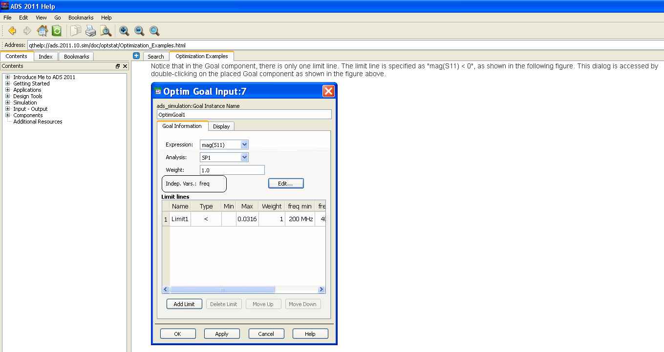
Firstly, according to ADS Help with this topic ?Optimization Examples? and Example 1: Continuous Optimization, we have to define frequency as Independent Variable. Here is its photo from ADS Help which I addressed before.

Secondly, according to another Help from Agilent ADS with this Link (page 12): http://www.utdallas.edu/~rmh072000/S...les/5B_lab.pdf
We have to define frequency as independent variable. However, after I remove frequency as an independent variable, I gain better results. Why?! As I said the two references use frequency as independent variable!
Thirdly, about amount of S11 and S22 which you have proposed them to be -20 dB I should say you are right. I have adjusted them at S11=-40 dB and S22=-60 dB that I should say their amount are not real, but I want to be discrimination between S11 and S22 because I need S22 to better (matching for LNAs). So, I adjusted them in this way.
Forth about using feedback to make a better matching, I still do not know how it can match better. Do you have a document about it or I should search it in IEEE?
- Different Input/Output matching
- How do you choose input power while doing loadpull?
- Why an input inductor required in all GPS LNA?
- Input and output impedance matching in Distributed amplifier
- In distributed amplifiers, is it total input capacitance of the gain stage or Cgs
- curve fitting for input and output matching
