Coupling co-efficient v/s voltage or current ratio
Literature says V1/V2=I2/I1=1=turn ratio
This is not intuitive to me. If the coils are slightly displaced so that coupling is weak then how V1=V2? It should be less..right?
I understand that M12=k*sqrt(M1M2) will reduce but why not the induced voltage?
It's for an ideal transformer with a coupling coefficient k=1 and lossless.
Hi johnjoe,
I know that its for an ideal transformer. My question is how do you express analytically for non ideal case?
The assumption in your first post is wrong, the voltage is of course reduced for k < 1.
There a different methods to describe coupled inductors and it's important to clarify which model you are using. A straightforward model, that's often used in EM analysis of arbitrary conductor geometries is an impedance matrix:
Zij = Rij + ωLij
Vj = Ii*Rij
You feed a current into branch i and get a voltage at branch j.
For the simple case L11 = L22, you get L12 = L21 = k*L11.
Hi FvM,
Thank you very much!
1. Can you suggest me a simulation technique/paper for finding k i.e coupling factor from a kit inductor model provided by the foundry ?
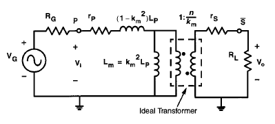
2. Also I have attached a model of a balun from IEEE paper. Is it possible in momentum to extract the values of lumped components ?
<a title="transformer_model.png" href="../imgqa/eboard/Antenna/rf-lbiouedgor4.png"><img src="http://obrazki.elektroda.pl/7931295500_1411769686.jpg" alt="transformer_model.png" /></a>
<a title="transformer_model.png" href="../imgqa/eboard/Antenna/rf-lbiouedgor4.png"><img src="http://obrazki.elektroda.pl/7931295500_1411769686.jpg" alt="transformer_model.png" /></a>

The shown model is in accordance with the transformer description in SPICE, L1, L2 and k, additionally winding resistances.
But which model representation do you want to map to it? Any example?
Hi Fvm,
I have an inductor model from a CMOS process foundry (runs in spectreRF). I want to represent the inductor using lumped components as shown in figure. How can I extract the equivalent values?
What do you mean by example of model representation? I dd not understand.
How are the model parameters given, impedance matrix, s-parameters, otherwise?
Coupling efficient voltage 相关文章:
- problem: coupling coefficient for two hairpin resonators
- Loose Coupling for a coaxial resonator
- Methods of decreasing the coupling between two closely placed antennas
- Re: Polynomial synthesis in coupling matrix technique
- Capacitive coupling between coaxial and coplanar circular coils
- Increasing stages coupling without increasing capacitance in TRX
