SSB modulator or VSB?
I have found this circuit http://www.seekic.com/uploadfile/ic-...4216472392.jpg and the author claims that it is an ssb phasing modulator.
Is that really an ssb phasing modulator or a VSB modulator?
I can't view that image, I see the very top then an error message that the file is corrupted. Can you post it directly please.
Brian.
Here it is Brian
Thanks,
it certainly isn't VSB. At first glance I would say it was DSB with supressed carrier but that makes the USB/LSB switch meaningless. I can't see how swapping the audio phase reverses the sideband though. By implication, you could reverse the microphone wires to get the same effect!
Brian.
I guess there is lot of rubish on the internet...
Thanks a lot Brian
I suspect that somebody has horribly misunderstood the phasing method of SSB generation (Where flipping one of the I/Q baseband components does indeed change the sideband.
That is a not very good DSB modulator as far as I can see.
Regards, Dan.
It's principally a DSB modulator but it may also work being as SSB-Mod. by changing C2,R1,R2 value who shifts the phase of the carrier in a tricky way.
But it's definitely not a real SSB-Mod. VSB Modulators use very sharp filters and VSB cannot obtain by playing SSB methods.They are essentially used for old-fashion analogue TV transponders.
What sort of SSB performance do you expect from such a circuit?
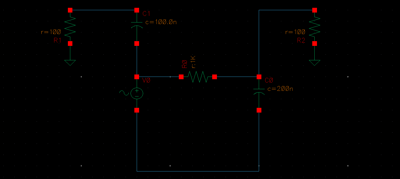
The baseband/audio signal is phase shifted by 1K and 0.1uF cap. circuit ( of course they shift the phase in a pretty narrowband ) and it gives you "roughly" 0/90 degree signal ( let's say I/Q signals) and on the other side the carrier phase shifted by C2,R1 and R2 components by 90 degree ( this will be valid for single frequency or in a very narrowband-RC technique) and finally a poor SSB is obtained.
How is the audio shifted?
I would buy it if T4 secondary had a centre tap to ground or suchlike, but without that the audio output is purely differential across the 1K resistor with the cap simply forming a highpass.
Even with the (I suspect) missing centre tap in place it is a horrible circuit.
Regards, Dan.
Regards, Dan.
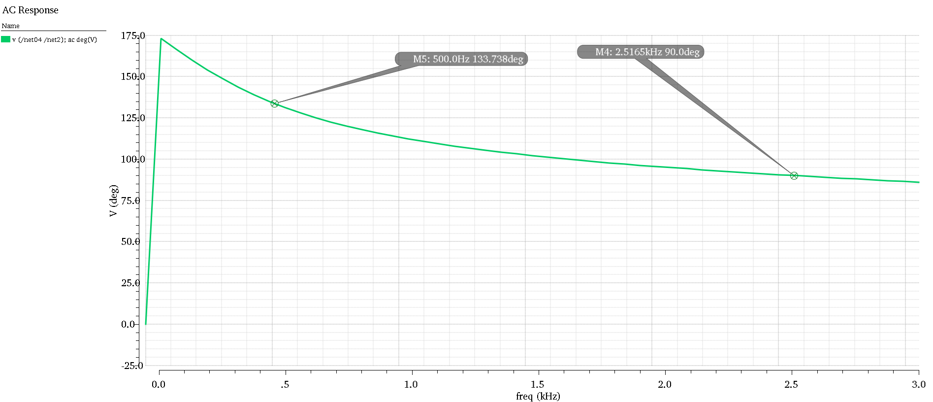
That .1 MF just above AF amp, produces a leading phase, the other out via the 1 K +.1MF produces a lagging phase to the audio, so the difference must be 90 degrees across the whole audio band
The only way to produce VSB is to filter out the unwanted products.
Frank
Like this...


Still not seeing it sorry.
Start at that switch, and work downwards, the circuitry forms a single loop with no ground reference, and a two terminal source (which is what this is) can only have 180 degrees between its terminals.
I suspect that your sim is playing you false here.
If the transformer secondary had a centre tap, then it might be possible, but what is effectively a two terminal voltage source with a series/parallel rc network? No.
Note that this thing will develop a phase shift relative to the input of the transformer, no surprise it is a filter after all, but it is physically impossible for the only two output connections of a floating network to have anything but 180 degrees between them (The currents would not sum to zero, and i will take basic physics over the sim).
Regards, Dan.
I've built this circuit while ago, just for fun, and I guarantee that is a fake.
Is doing something in terms of side band suppression and also on carrier suppression, but the resulted modulated signal is distorted and non-intelligible, whatever invented demodulator you use.
The transformer is replaced a differential voltage source here, so GND reference is not necessary because the thing which is important here the phase difference between two nets.Since this phase difference is maintaned over a band ( obviously quite narrow ) it'll roughly be obtained a 0/90 degree.If we talk about differential system, GND reference is not necessary.
Consider a relative phase difference between the nets, not absolute.In additional to, the loads are not purely resistive and phase shift behaviour can be provided in a tricky way.
OK, it's not a real circuit but it should somehow work ..
How can you have a phase difference (other then 180) between the two connections to a two terminal generator? Current flows in loops always, so for the two signals to be different you need to reference them to a third terminal, and not just each other, this is very basic circuit theory (Sum of currents at a node, sum of voltages around a loop).
You only have a single two terminal floating output, you need at least three terminals to define two independent signals, a reference (ground), I & Q, there is no ground connected to that secondary circuit so the output can only exist between those two connections, and speaking of phase between only two ports on a two port generator is meaningless.
The voltage across each of the 'output' resistors is trivially Ir, but as they are the only things connected to earth Ir1 + Ir2 = 0, so Vr1 = -Vr2, no useful phase shift there.
Trust the physics before the numerical stability of the sim.
Now maybe you get a phase shift relative to the transformer primary (you do) but that does not help here.
Regards, Dan.
... but the bottom line is...
dont bother building it.
Even if there was an audio phase shift (which I still can't see) it would only be 90 degrees at one frequency so I would expect incomplete cancellation of the carrier as the modulation moved away from that frequency. In my opinion, if all the adjustments were optimized, you would have a poor performance DSB modulator and nothing more.
Neazoi, if this is in conjunction with your other posts about quadrature VFOs, the better method would be to use an audio polyphase network and two balanced mixers. It should give good frequency response and true (reversible) SSB output.
Brian.
- 80m phase shift SSB transceiver, How does it detect USB/LSB?
- ssb radio replaced VFO with DDS and the high-pitch noise started
- SSB generation by shifting audio spectrum
- SSB VS DSB in linear amplifier
- CA3083 vs TCA671 in ssb push pull linear, which one is more powerful?
- AD7008 can be used for SSB modulation?
