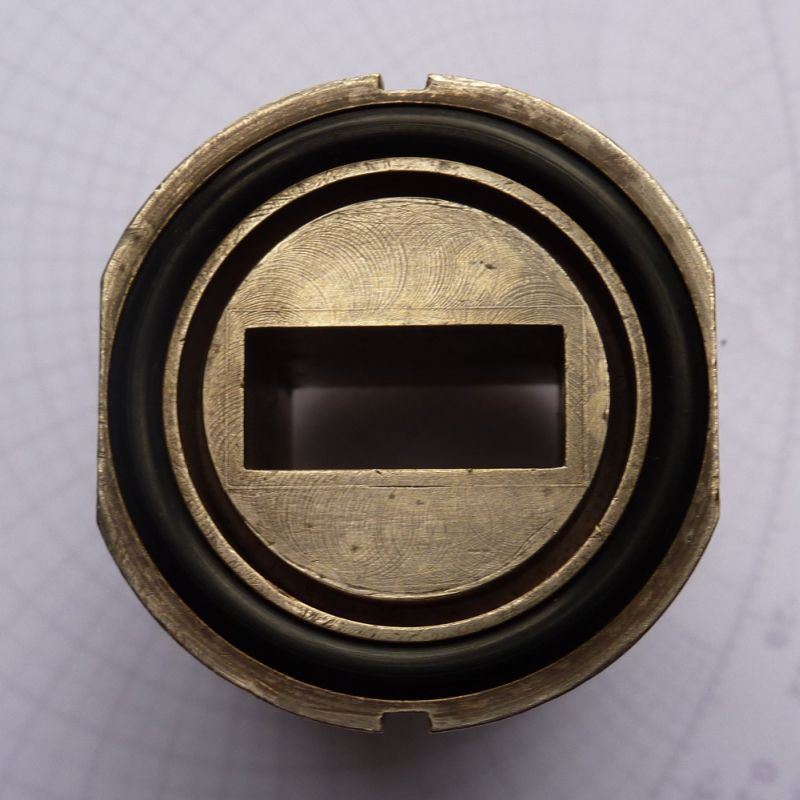
Microwave Oven Door Perimeter Seal
The cavities are formed from a bunch of bent tabs 3/4 inch wide, 3/4 inch deep, and are spaced every 3/8 inch apart. My oven door has about 40 of these bent tabs.
I assume these have something to do with keeping the microwaves from leaking out through the cracks around the door. With my brief experience with microwave guides I found that it was very difficult to keep them in my home made guides. All the seals between two wave guides would have to be machined very flat and the bolts would have to be well tightened. Even very small gaps would leak a large amount of power. The edge seal around the door on a microwave is no where near this quality of seal yet it still works very well.
What I would like to know is: how do these cavities prevent the microwaves from leaking out. What makes them work?
The cavities are quarter wavelength deep. They have a short circuit at the bottom, so they reflect an open circuit back to the door frame. Open circuit, no current, no current, no power!
Wave guides normally have a groove on their mating flanges to do the same thing.
Frank
As Frank hinted at ..... doing waveguide joints correctly, you would NEVER mate 2 flat flange surfaces. it WILL leak
you also wouldn't two choke flanges
one flange must have the 1/4 wave slot/groove in it these are called choke flanges

cheers
Dave
All wrong, gentlemen! The chokes are half-wave long as the required effect is to create a perfect short at the door (and waveguide) gap.
A quarter-wave shorted section of a line creates "open" or a high-impedance effect across the gap.
The half-wave length is not only the choke depth, it includes another length to the gap at the door-frame, to reflect any "leak" back to oven cavity.
Most oven doors do not leak at all if the hinges are not worn. You can detect strong leaks around knobs, power cable and lamp door. Ovens with foil keyboards almost do not leak.
yes indeed it is ~half wavelength from the back of the slot to the mating surface.
A ferrite bar in a nylon or fiberglass+ neoprene sleeve becomes the strong lossy RF absorber on the door seal or on both sides around the edge to attract and absorb the stray energy. Half wave choke provides best path for leakage to follow and get absorbed locally rather than radiate out the slot antenna.
The Ferrite for microwave unlike for SMPS is low mu and very conductive (but lossy) with metal particles which also helps conduct any heat evenly and overall makes the design very tolerant to small gaps.
good grief, don't be so over dramatic .... not all wrong
OK so we both boo-boo'ed on the depth that's all
Dave
were we half right?
Frank
I take back my apology ... @jiripolivka you are the one who is wrong
here are 3 listed links to microwave flange info stating that Frank and I were correct
you really had me second guessing myself needlessly
Maybe you need to do a little revision
cheers
Dave
Engineers' Handbook of Industrial Microwave Heating
https://books.google.com.au/books?id...%20%3F&f=false
http://www.radartutorial.eu/03.linetheory/tl13.en.html
http://www.rfcafe.com/references/ele...-1-31-1-40.htm
Navy Electricity and Electronics Training Series (NEETS)
Module 11?Microwave Principles
Chapter 1: Pages 1-31 through 1-40
Dear Dave and others:
Please learn transmission line basics:As I wrote, the idea of a perfect short at the gap between the door and frame , and between waveguide flanges , is based on a shorted half-wave section. That the groove is not exactly a halfwave deep is not important. The complete way from the groove end (a short) to the door-frame gap must be half-wave long.
The discussion became a bit unfriendly last week so that moderators felt compelled to close it for a while. Hopefully we can clear the open questions now.
I was asked in a mail
jiripolivka emphasized that the choked waveguide flanges implement 1/2 wave (short-to-short) transformation. So what's the role of 1/4 wave dimension in this designs?
I think, the picture shown below (from my favourite German Taschenbuch der Hochfrequenztechnik by Meinke/Gundlach) can give an idea. You see that the total stub length is λ/2, with a bend in the middle. The bend point distance from the waveguide wall is λ/4, associated with a current "knot" of the standing wave. So leakage into the inter-flange gap (marked as "Kontakt") can be effectively cancelled.

is that pic for a microwave oven or a waveguide choke flange ?
I accept that there my be considerable differences between uWave oven doors and waveguides and their choke flanges
FvM, what is that kontakt dark line ? kontakt = contact ? contact with what ?
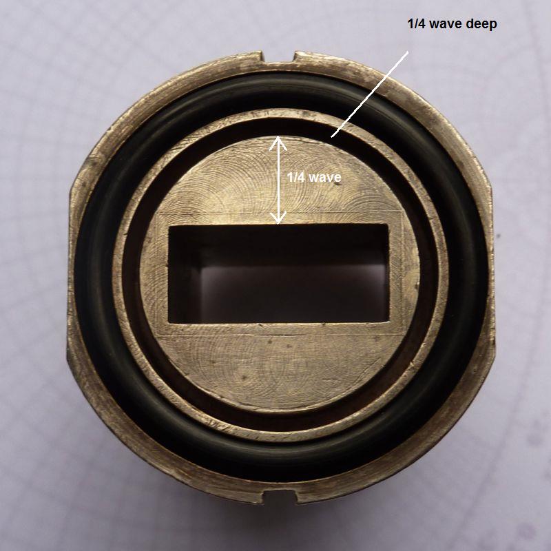
annotated that pic of mine above ( which is the same as all my 10GHz choke flanges)

Dave
The picture shows a waveguide flange. The dark line is part of the gap between both flanges. It's almost identical to the "choke joint" figure in the radartutorial.eu link, except for the direction of the first gap segment which doesn't matter in transmission line terms.
The potentially misleading point is that the figures don't refer to the obvious, the 1/2 wave transformer property of the complete design.
For the oven door design, I would prefer to see a scheme of the initially discussed geometry.
ohhh crap ... I have just seen the error of my ways
and just done a measurement putting a straight edge (as shown by the thick white line on the right pic) across the full flange
there is a 1mm gap between that inner section of the flange leading to the slot and the bottom of the straight edge
To be honest, I don't know if I have ever noticed that before and didn't recognise it from the drawings
well talk about being red faced :(
sorry for my arguments
Dave
Thanks, David and Jiripolivka,
It is the first time that I see the inner gap.
And I am curious about the 1mm gap, how long opened in the inner cavity? 1/4lamda?
Or just along the inner perimeter? all inner cavity is cut?
hi Tony
on the left section of my image where you are looking straight on to the end of the WG
Everything inside the ringed slot ( the bit with that blue 1/4 wave arrow on it) is lower than the rest of the flange that is outside the ring
Dave
Thanks, Dave.
Although I have seen various flanges from S band to Ka band, but in S band the slot filled with rubber seems not 1/4 lamda of S band. Am I right?
