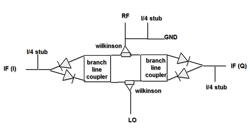
Why in IQ balanced mixers diodes are not isolated at low frequency?
Source of my doubt are diagrams in my RF book and few internet sources, for example tutorial on mixers at QSL.NET. It is shown that RF and LO comes through High Pass Filter (HPF) to mixing diode, and then through Low Pass Filter to the IF output. The question is why HPF part is absent on all microwave mixers i have seen? To me it is obvious that microstrip can't block frequency of 5kHz. In upconverter mixers somehow diodes are driven with different waveforms, although there is direct microstrip path between each channel. I think that there must be high pass capacitor before mixing diode, but there is no any, and i do not understand why. At least quadrature mixers must have that capacitor to block different channels low frequency signal travelling from one diode pair to another.
I think the question is useless without referring to specific circuits. Balanced mixer is primarly a signal processing function, there are different ways to implement it, e.g. using transformers or phase splitters.
Circuit schematics, please!
Here is an example:

I can see direct path between I and Q port (microstrip lines + diodes). Although it works and we can get different phase signal on I and Q port. Why I-port signal can't reach Q-port? Through diodes and microstrip line.
RF cancels out at the IF ports in a first order, the residuals are blocked with the λ/4 stubs.
i meant low frequency IF signal itself. it can travel between port after mixing? For IF signals stubs and other microwave stuff does not apply
