Printed omnidirectional loop antenna
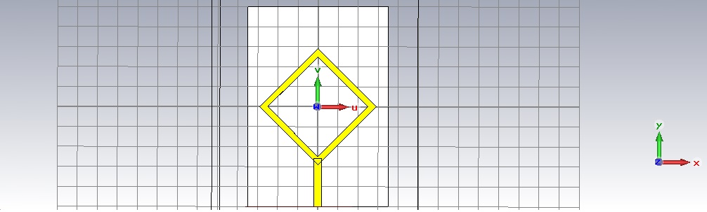
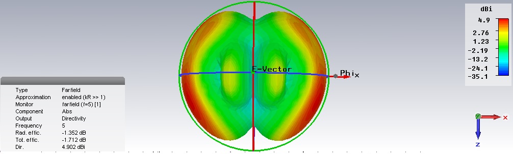
The closest one that could give me an omnidirectional was the diamond shaped loop antenna. However, there are only 2 strong points on the XZ plane of the radiation patter. I need to get donut shape radiation pattern.
I do not know how to continue to improve to make it omnidirectional radiation pattern. Also, the frequency range I need is from 5 - 6 GHz. Your help and input is greatly appreciated.
Anyone? Let me know if there are any guides on achieving an omnidirectional printed loop antenna.
a theoretical loop should be exactly omnidirectional. So if it is grossly directional, then you must be feeding it oddly. Are you coupling in using a smaller loop, etc, or just hooking up a 50 ohm grounded line to it, center conductor to one side of loop, and coax shield to the other end of loop (which will not work, of course--the coax line shield will be a big part of the antenna)?
... if the diameter is electrical small. So what is the loop diameter here?
Thank you for your reply.
I am not sure what you mean by smaller loop, but the loop length is about 59mm.
I designed a stripline feed port similar to microstrip antenna. Would a different feed method works? If yes, a good example would be?
To be clear, I have included pictures of what I am getting.

Your loop is not electrically small at the operating frequency, and it is not a loop antenna. In a loop antenna we have circular currents flowing in the loop. Your feed is different (not useful for loop antenna) because it does not create loop currents.
Just to be clear, it is not a loop antenna because of my feed port am I right?
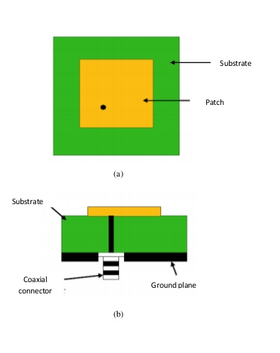
Should I have a feed port that connects directly from the bottom through the substrate to any side of the loop? Will that work?
(Something like this)
Also, in the work above, I did not have a groundplane. Is groundplane necessary to achieve an omnidirectional radiation pattern as well?
That's a patch antenna, not a loop.
What do you mean with "did not have a groundplane"? A minimal ground plane as in the drawing or no ground plane at all?
In any case, the feed cable sheet will act as ground and change the antenna characteristic, most likely in an unwanted way.
My general suggestion is to review an antenna text book like Balanis Antenna Theory to get at least an overwiev about patch antenna design methods before proceeding with your project.
Yes that is a patch antenna. I was referring to the way it is fed from the bottom through the substrate upwards.
I did not put any groundplane at the bottom. Will this affect the radiation pattern? Or am I totally wrong in not putting any groundplane?
"feed cable sheet", do you mean the stripline?
Yes I understand that reading the book will give me more information but it will take some time for me to finish reading it which I do not have the time now
So you suggest that others their spend time solving your problem, because you are too busy?
I am not suggesting anyone to solve my problem, in fact I have done the design and I did something wrong which you pointed out, thanks.
I only have basic understanding of designing an antenna. I apologize if I asked too much questions.
Thanks for your help.
For some reason I overlooked the post #5 drawing (with stripline( and referrred to the post #7 schematic.
Now regarding post #5. If you have no ground plane, where do you connect the port? A port connects between two conductors, no matter if the other side is an (ideally) infinite groundplane or another dipole arm. Any finite groundplane can be also seen as a dipole arm.
No problem.
Thank you for pointing that out Will try and get back here again if there are any problems.