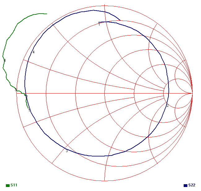
Network Analyzer shows positive S11 on passive PCB
Can you show the polar display of S11 (Smith diagram)?
Your fixture and adapters must be included in the calibration.
Then insert DUT for accurate readings.
Thank you SunnySkyguy. I calibrated the VNA to the end of the test cables, and I have SMA connectors soldered directly to the PCB. Do I need to include the SMA connectors in the calibration? If so, how?

Looks like a wrong open/short calibration.
Are you seeing positive |S11| using the factory calibration, or user calibration (with passive networks attached)? If the former, then something is either wrong with the instrument or the factory calibration.
I used the Agilent 85033C Cal Kit. When I finished the Cal procedure, I re-checked the short, open and load terminations on the VNA's Smith Chart, and they were correct.
So I am puzzled by the positive S11 response.
It's matter of calibration. Have a look to this:
http://anlage.umd.edu/Microwave%20Me...980-2784EN.pdf
Sure it matches because you used them for calibration, but I think it's not a broken standard, otherwise s22 would be strange too. Try to change cable and connectors of port 1.
Thank you all for your help. I tried a different Cal Set and results were substantially closer to predicted (simulated) results.
- Positive or negative to have a bandwidth > cohererance bandwidth, why?
- Analogue spectrum analyzer marker and tracking generator plugin
- Trouble with my analyzer ?
- How do I know if a spectrum analyzer is enough to measure an specficic DAC?
- Network analyzer calibration for RF test points
- 60dB attenuator prior to spectrum analyzer, how to?
