1dB Compression Point in LTSpice
What does it mean ? This circuit has no input, what P1dB compression point you're looking for ?
P1dB is a nonlinearity concerned metric and it's ised to charaterize Amplifiers,PAs,LNAs,Mixers, etc. so the "driven" circuits.
You got an modulated oscillator then an amplifier... it doesn't make sense...
Okay let's say I am supposed to do it based on the oscillator and power amplifier alone? How am I going to go about it?
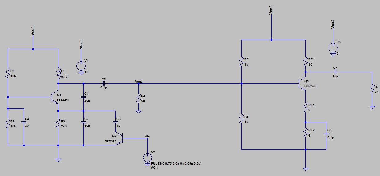
The first stage is a oscillator where I am supposed to pump a signal in at Q2 using a pulse. The second stage is a power amplifier.
There is a mistake in the schematic, you have the 50 ohms load (R4) in parallel with R5, which is one of the amplifier DC bias resistor. You need a series cap for DC blocking.
It is to simulate the impedance of an connector when doing hardware implementation
The compression point can be determined for the amplifier.
Use sine input source in transient analysis, for an exact compression point measurement, determine fundamental wave in fourier analysis, determine with which input level the gain drops by 1 dB. You'll get approximately the same result by looking at output AC Vrms.
Compression dB LTSpice 相关文章: