What is "The zero frequency in passive filter" of a PLL
I am interested in PLL recently. I read some posts on this forum. It mentioned:
The zero frequency in passive filter
What does it mean? Could you explain it to me?
Thanks,
I think you are talking about zeroes in the filter transfer function. In other words, frequency values where the transfer function equals zero. These are the opposite of "pole frequencies" which are frequencies where the tranfer function is infinity.
Hi,
Here is the source thread of the question.
https://www.edaboard.com/thread79870.html
Could you confirm that?
Thanks,
A zero is a root of the numerator of the transfer function.
Each zero gives a +6 dB/octave, or +20 dB/decade response and a single-pole section will have a 90° phase shift at the crossover frequency suitable for adding phase margin to the stability of a closed loop at unity gain.
If we have a zero at the origin, that is a zero in the numerator, the filter will have no response at dc (high-pass or band pass).
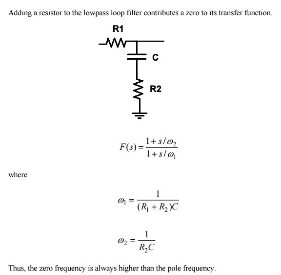
For example in a PLL; a simple filter is like below.
But a practical PLL phase detector loop filter one may have a smaller C such as C/10 in parallel across C+R2 to reduce phase noise a bit more without serious reduction in phase margin, which results in instability or ringing or phase error.

the transfer function we are talking about is "THE OPEN LOOP TRANSFER FUNCTION". I.e. the PLL is actually broken so there is no feedback. You can simulate this OPEN LOOP transfer function, plot the gain and phase on a BODE plot, and where the open loop gain crosses 1 ( i.e.0 dB), your phase had better be no closer than 45 degrees to 180 degrees. this criteria is called "PHASE MARGIN"
by manipulating the pole(s) and Zero(s) you can usually achieve this. a common way is a "Lead-Lag" filter.
IF you had a PLL circuit with a VCO and the passive filter that SunnySky showed, you would have one pole at zero frequency (from the VCO), and another pole due to R1 C. each pole gives you 90 degrees of phase shift, so your open loop transfer function would have 180 degrees of phase shift, and by definition you would have NO PHASE MARGIN and a PLL with horrible peaking. So you add the R2 to add a zero, so that when the gain crosses zero, the phase of the whole open loop system is far from 180 degrees.
google control loop theory
