[How to] Lumped elements conversion into Distributed elements
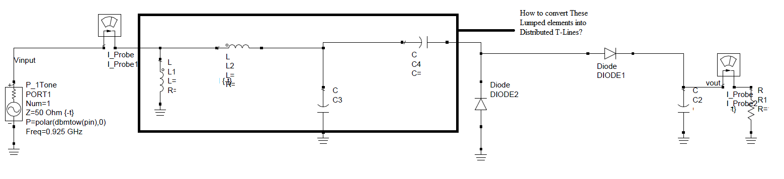
I would like convert the lumped elements in the following design to equivalent distributed elements for fabrication purposes. Can someone kindly suggest some methods, online tools or simulators for that matter?
Awaiting replies,
Regards
L1:Short circuited stub
L2:MS Transmission Line
C3:Open circuited stub
C4:no equivalent..
@BigBoss Thankyou for the T-Lines description. But can you kindly let me know which method or simulator u used for the design?
Using what for waveguides? Optical fiber?
Due to the fact that you're operating around 1 GHz, I would recommend something like microstrip or coplanar waveguide on FR-4, but since the values of the components aren't specified, it's hard to make a recommendation.
You don't need a simulator...Just a piece of paper and a pencil..
Good one :).. So whats the method to work on paper
... and a lot of PCB area. There are these cases where distributed elements make sense. But here at 1GHz, it is much better to use small SMD instead of large transmission line structures.
Any standard microstrip design book will have the details for implementing those L and C on planar geometries..You can refer to a solved example in Pozar book (Chapter on filters) where the process of implementing series and shunt L and C is explained..
Thank you all for ur kind replies.
Another resource to show the equivalent transmission line elements:
http://www.rfcafe.com/references/ele...components.htm
But at 1GHz it makes not much sense. Use SMD instead.
You can either transform the lumped components into TLs or stubs. Only series L and shunt C can be transformed into TLs, stepped impedance lowpass filters are typical examples of lumped>TL transformation. Because you have series C and shunt L, TL transformation is not applicable.
You need to perform stub transformation, see Richards transformation formulas, it replaces the lumped components with stubs(short or open). Once all the components transformed into stubs you need to go one step ahead and transform the series stubs(because series stubs can not be implemented in microstrip) into shunt stubs using Kuroda identities. After all, you end up with all shunt stub filter, their width(trace width) may or may not be practical! If you are happy with them you can manufacture it.
All these efforts may not be necessary to make a design at 1 GHz. Working with lumped components sounds better.
@ferdeem ,Thanks for the detailed reply :)