180 degree hybrid using Lumped elements
I am looking for help in designing a 180deg hybrid using LC elements only.(A hybrid that works like a power splitter). The center freq is at 2GHz.
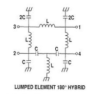
I've tried lumped element rat race topology(shown below), but it gives too much loss with spiral inductors.
Is there any other topology that will give me similar result but less lossy?
If you have a sufficient space, you can realize this with Microstrip ( or similar) Lines.It will be less lossy..
What technology do you use - SMD components or PCB spirals or RFIC/MMIC spirals or ... ?
They are MMIC spirals from GaAs process.
I need a compact model. Using quarter-wavelength microstrip line at 2GHz is too long.. If there any other lumped element topology that consists less inductors?
Have you optimized (tuned) the inductors for best possible Q factor at your operating frequency? For a given L value, less turns gives better Q, width and spacing must be adjusted depending on the f(Qmax) vs. operating frequency.
~~~
I don't know your application, but would a lumped element balun do the job?
http://leleivre.com/rf_LCBalun.html
Thank you for the link and reminding me the Q of L.
the balun probably won't help because L is ~4.7nH at 2GHz. this large spiral inductor is too lossy.
I am thinking of any possible topology to reduce the use of inductors. do you have any suggestions?
If you work on a GaAs substrate, the losses will not come from the inductors only, the MiM caps will add some loss into overall circuit performance.And this is inevitable.
If you intention is to create 2 signals by 180 degree phase difference, you may also use a transformer.It will be less lossy. (I realized a such transformer long time ago on Si that works 2.45GHz, the loss was around 1.8dB-2.2dB)
I've done a quick inductor design for 4.7nH in a GaAs technology, with 2.5 turns sqaure shape.
Technology guess in this design: 0.7μm top metalization. Q is ~11 at your 2GHz design frequency.


Thanks for your simulation and sorry for the late reply. I was busy studying... So on my latest work, I realized the hybrid using T-network for both 90deg and 270deg lines, then use less turns for each inductors.This give me pretty good results. It's ~1.5dB of loss. I originally do pi-network for 90deg and T-network for 270deg because I thought less inductors would gave less noise.
Thanks again for the help!
Thanks BigBoss! Yes, MIM caps add noise too, but it is minor compare to inductors right? I am keeping the lumped element model with all T-networks. it gives me ~1.5dB of loss, which is close to your transformer solution. Thanks for the suggestions.