Waveguide Switch, Magnetically Latching type, actuator
The waveguide switch latching type remains in the last position without any holding current. I would like to know how is this behaviour achieved. I have several questions pointing in this direction:
1) MOTION: Which device is used to move the rotor? A stepper motor? or... just several solenoids?
2) POSITIONING: As there is no holding current. How is done the latching? By a magnetic field created by permanent magnets? With the detent torque of the stepper motor?
3) How is possible to achieve a properly and accuracy alignment between rotor and stator window?
Thanks in advance for your help!
its a mechanical mechanism. buy a cheap one off of ebay, and take it apart.
Electro-mechanical waveguide switches use a special rotary solenoid-driven magnetic rotor that turns 180 degrees upon a current pulse. It is a similar design like step motors, only it has two steps per one revolution.
Magnet itself locks the rotor position within 1/2 degree, and to indicate the position, simple contact or a reed contact is used.
Some designs also use a motorized gear but as the mass of the rotor is small, complexity is not needed.
In electrically controlled waveguide attenuators, motorized gears are common, with DC or step motors. Real-position feedback is made by a precision potentiometer linked to the gear.
In both devices, manual overdrive is possible by turning the drive.
Thank you very much for your answer Jiripolivka. Some more questions:
1) When there is 4 positions, 90 degrees are needed. So 2 coils are used? In fact, for satelites, rotor tipically has 3 waveguide paths (45 degree positioning is needed), so 3 coils in this type?
2) When you said "magnet itself" you mean additional permanent magnets in the stator? Because the solenoids will be deenergized after the pulse.
Thank you very much in advance!
The wave guide switches I have , have a "Geneva" mechanism inside them which latches them very accurately. The actual motor is like a conventional DC motor turned inside out with the rotar stationary and the magnet moving. Instead if having a commutator, there are microswitches to switch the current in the coils . I believe these were of the highest quality as we used them on satellite uplink transmission equipment. If you want me to, I'll inspect one tommorrow.
Frank
Hi Frank!
Thank you for your information. I have also seen the geneva mechanism in some manufactures. But this mechanism does not latch or lock. It just changes rotary continous movement to a discontinous one. I mean it may be a good mechanism to move the rotor to the new position, but not to clamp it.
If you could inspect one I will be really gratefull. Thanks a lot for helping me Frank.
Those designs I referred to use the rotary permanent magnet and a fixed solenoid, and turn by 180 degrees. Then there is a gear reducing the switch-block rotation to 90 or 45 degrees, and the Geneva mechanism in some designs.
Manual overdrive looks like a turning knob and another magnet locks the rotary magnet at stops.
Open one to see its design. Motorized drives are also used but more complex gears are needed.
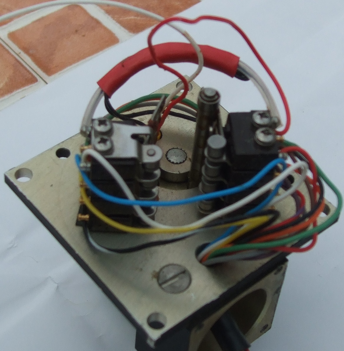
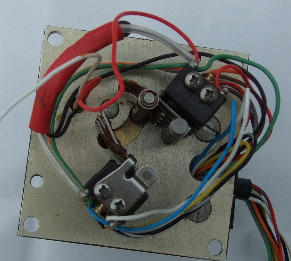
here are some poor pictures:-


I was mistaken about the Geneva mechanism, this one stops by the virtue of the magnets pulling on the stator cores , but being stopped by the microswitch actuating arm running out of "slot". So its the position of the curved slot in the base that locates the position of the switch. Shown in pic 1.
The switch is labelled SMU-1PL1-3P Sector microwave industries,Dear Park, NY
Frank
Hello Frank,
Sorry for my late reply. Thank you very much for the pictures and for your time, pictures are great. Does this switch allow just 2 positions (180 degrees)? I mean at the two ends of the slot stroke. I just can see 2 windings, that also makes me think about just 2 positions.
I was also searching information about actuators and I found the following patent: http://www.google.com.ar/patents/EP1560286A2?cl=en
The latching force at the stable position is achieved by the minimum reluctance positions (minimum gap between stator shoes and rotor maximum radius regions). In this patent they use the rotor permanent magnet and ferrous stator to create magnetic forces. But I still can't understand how they achieve high precision positioning by magnetic forces. I can not understand how this "60 degrees stepper motor" can face the waveguide flange against the switch window with high accuracy in all positions.
As the magnets are pulling the rotating part around to align with the soft iron coil armature, the rotation is stopped by the long pin (that operates the microswitches) running into the end of the curved slot (pic 2).
Frank
