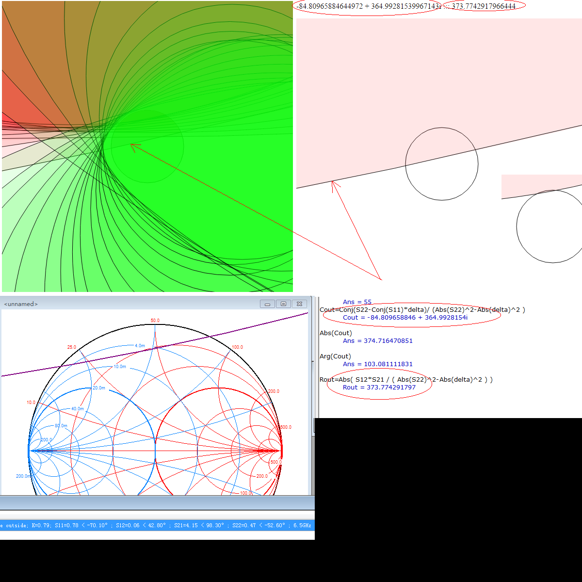
Stabilizing LNA problem. Stability circles precision question about Smith V3.10.
时间:04-05
整理:3721RD
点击:
While comparing my calculations of stability circles i compared it to Smith v3.10 program and found one problem:
i am using NE3210S01v1_2-18_2_10.S2P file as data source. Problems occur at frequency of 7.5GHz, where output stability circle (instable outside) overlaps reflection=1 circle in much bigger area in my case. I rechecked formulas with SpeqMath. And as other circles on input and output looks similar to Smith v3.10 program formulas must right. Also i rechecked my formulas with examples in few papers to find stability circle centers and radius. But then i noted that in Smith v3.10 S11 coefficient is written as S11=0.78, although in data file S11=0.699. So i changed this line in s2p file to check this idea:
then output stability circle in my calculations moved out of smith chart, and started to look more similar to Smith v3.10.
Does this mean that small variation in this parameters affects stability circle very much, and it is better to choose bigger stabilizing rezistor for example (bigger than value obtained by constant-resistance or conductance circles)?

i am using NE3210S01v1_2-18_2_10.S2P file as data source. Problems occur at frequency of 7.5GHz, where output stability circle (instable outside) overlaps reflection=1 circle in much bigger area in my case. I rechecked formulas with SpeqMath. And as other circles on input and output looks similar to Smith v3.10 program formulas must right. Also i rechecked my formulas with examples in few papers to find stability circle centers and radius. But then i noted that in Smith v3.10 S11 coefficient is written as S11=0.78, although in data file S11=0.699. So i changed this line in s2p file to check this idea:
Code:
!      f            S11               S21               S12               S22
!     GHz      MAG      ANG      MAG      ANG      MAG      ANG      MAG      ANG
     7.50    0.699    -82.7    4.170     85.3    0.065     36.6    0.423    -59.2
to
     7.50    0.7      -82.7    4.170     85.3    0.060     36.6    0.42     -59.2
Does this mean that small variation in this parameters affects stability circle very much, and it is better to choose bigger stabilizing rezistor for example (bigger than value obtained by constant-resistance or conductance circles)?
I have additional layout question. How to put input and output series or parallel stabilizing resistors? For example FET with common source. I want to put stabilizing resistor from drain to ground. There must be decoupling capacitor, as drain connected to voltage source. If it is series resistance, wich position is better? Near device before matching network, or farther, after it?
From what i understood, for some s-parameters combinations additional care must be taken. As in my first post, small rounding errors lead to big change in stability regions at 7.5 GHz. If anybody have comments, please comment.
Stability circles Stabilizing 相关文章:
