Using Z-Parameters to find input and output impedance
时间:04-05
整理:3721RD
点击:
Hello all,
I made some 2-port measurements using a a VNA and needed to deembed a length of transmission line. So i converted the S-parameters to ABCD, did the matrix math to remove the t-line then converted back to S-parameters.
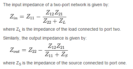
I need to know know the input and output impedance so i converted the deembedded S-parameters to Z-parameters. For the longest time I thought Z11 and Z22 would represent my input and output impedance but I ran across:
Have I been interpreting Z11 and Z22 wrong all these years? Should I be using the equations above to solve for the input and output impedance?
Side question: If i had a one port network would Z11 be in the input impedance?
Bonus question: I just realized the method I am doing only deembedds a length of transmission line from port 1. I want to remove an identical length of line from port 2 but my matrix math is a bit rusty. Using ABCD matrices, the initial condition is [tline][S][tline]=[measurement]. I can perform [s][tline]=[tline]^-1*[measurement] to remove the tline from port 1, but how do I go about getting rid of the second tline?
Thanks in advance!
I made some 2-port measurements using a a VNA and needed to deembed a length of transmission line. So i converted the S-parameters to ABCD, did the matrix math to remove the t-line then converted back to S-parameters.
I need to know know the input and output impedance so i converted the deembedded S-parameters to Z-parameters. For the longest time I thought Z11 and Z22 would represent my input and output impedance but I ran across:
Have I been interpreting Z11 and Z22 wrong all these years? Should I be using the equations above to solve for the input and output impedance?
Side question: If i had a one port network would Z11 be in the input impedance?
Bonus question: I just realized the method I am doing only deembedds a length of transmission line from port 1. I want to remove an identical length of line from port 2 but my matrix math is a bit rusty. Using ABCD matrices, the initial condition is [tline][S][tline]=[measurement]. I can perform [s][tline]=[tline]^-1*[measurement] to remove the tline from port 1, but how do I go about getting rid of the second tline?
Thanks in advance!
Znn is, by definition, the impedance seen looking into port n when the current at all other ports is equal to zero (open circuit). So if the other ports are open, then Z11 is your input impedance. For a one port network, Z11 will always be your input impedance.
This might relate to a transformer with impedance ratios that are defined by coupling factors to load ZL, but does not look right to me without coefficients of coupling.
1- When you work with a two-port network, Z11 is NOT input impedance, Z22 is also NOT output impedance. You have to use the equations which you shared.
2- In a one-port network, Z11 is input impedance.
3- Sorry, I have no experience about this.
find Parameters impedance 相关文章: