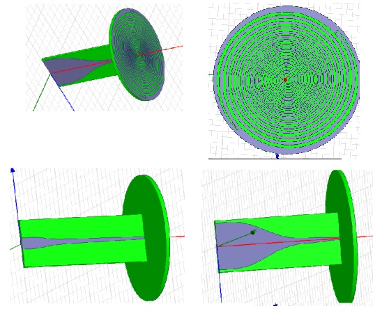
2-18GHz cavity backed spiral antenna pattern distortion
时间:04-04
整理:3721RD
点击:
hi everybody.
i am designing a cavity backed spiral antenna in 2-18GHz.
i used microstrip balun for transforming from 50ohm input impedance to 188ohm spiral impedance.
both balun and spiral have good behavior . and spiral have good patterns in all frequencies.
but when i attach this two part the resulting radiation patterns distorted in high frequencies (spetially above 14GHz).
please check attached pics.
in addition i wan to model an absorber(like AN75) in HFSS and i don't know what is the electrical properties(epsilon and mu and loss tangent) of absorbers .
i would be thankful if some experts help me.

have you checked current phase in balun
upload your file so that we can understand your problem.
- what's the rf cavity filter tuning principle
- Klystron output voltage, cavity field strength
- TE220 rectangular cavity resonance electic field maximums.
- What is meant by cavity backed antennas,what is the need for it .
- Doubt in designing cavity backed antenna
- Substrate integrated waveguide cavity backed dumbbell shaped slot antenna
