microstrip transmission line awr
If i use mrfsub for substrates, how to make five signal conductor. i have only fm2clin for two conductors.
:)
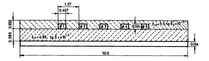
My interpretation of your drawing is that the bottom 124μm layer is the ground plane, so we have standard microstrip (MSUB element).
To simulate the 5 parallel conductors, I would draw them idependently with standard MLIN elements and simulate using EM extraction, so that coupling is included in simulation results.
You can also use the M5CLIN coupled line model
https://awrcorp.com/download/faq/english/docs/Elements/MXCLIN.htm
But with MSUB element we only make one dielectric, but on photo there are two.
You are right, I missed that. But as you said, there is no 5-coupled-lines element for use with the mrfsub. So the best (most accurate) way is to use EM simulation instead of the circuit model, and include the dielectric coating there.
microstrip transmission awr 相关文章: