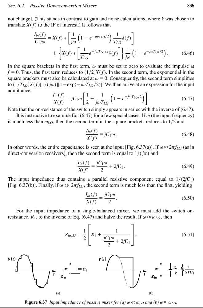
Frequency dependent resistance, mixer input impedance

So the input impedance contains a frequency dependent resistance. But what does this really mean? Writing the transfer function, it becomes clear that it consists of non-conjungate complex coefficients. This system produces a complex output from a real input. That makes no sense whatsoever!
What is a frequency-dependent resistance to begin with: Can it be physical, how to deal with it?
In this example, I have the gut feeling that it is just an approximated model. Indeed, if I just take the magnitude of the complex coefficients and look at the magnitude response it is reasonably similar....
The phenomenon of frequency dependent resistance can be find in any wire used to carry high frequency signals.
http://www.researchgate.net/publicat...f_a_round_wire
Why doesn't it make sense? Polyphase mixers exist.
I believe the 1/2fC resistance is the part due to so-called "harmonic reradiation." Basically the switching action across C1 causes power dissipation at high harmonic frequencies, but through the transparency of the mixer, this actually manifests as a shunt resistance that appears at the RF input fundamental. This effect is severe for mixers with a high duty cycle (like a single balanced mixer) but is less so for multipath mixers. This can actually be used to derive the minimum noise figure and conversion loss of various passive mixer types.
I have used this method of mixing in the past a couple times in products.
It is shown implemented as a S&H mixer.
When the sample duration is low duty cycle and the signal and sampling rate are equal, the difference frequency is the result and the waveform is exactly the same shape as the signal being sampled. So I used a sawtooth.
In my case I used the +zero crossing of a sine wave low level signal, f1 to create a 1% duty cycle one shot to sample a sawtooth signal derived from a similar stable f2 clock converted to a sawtooth waveform. Thus when f1=f2, the output is DC, and when signal being samples is a sawtooth, the Phase detector is linear.
This mixer output can be used for PLL or open loop for Doppler Shift.
The interesting part also is the effective series resistance of the switch is divided by duty cycle, so 1% one shot becomes Rx100 x C for the LPF response.
There are many other implementations.
resistance dependent Frequency 相关文章:
- Adding ports to know resistance at some point in 2-patch antenna
- Microstrip Negative Resistance Oscillator Nyquist plot Encirclement issues
- What is the gate resistance of the LDMOS?
- Calculating Resistance/Capacitance values from measured/simulated S-parameters
- MOSFET Resistance rout and Rds (ON)
- Negative resistance oscillators that designed wrong
