IMPROVING PERFORMANCE OF A COCO BY LOWERING IT's SWR/IMPEDANCE MATCHING
It is well known that a large number of DIY CoCo makers get frustrating results, and only a relatively small number get satisfactory or good results. Main reason is high impedance & resulting high SWR which causes the antenna to perform poorly even if it has a high Gain.
I have tried to find a method to ease out the SWR without using test instruments. I tested it and it gave me an improvement of about 25 to 35%., not optimal, but better than nothing.
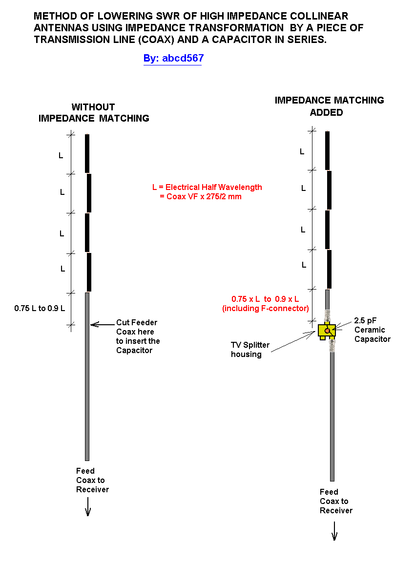
Please see sketches below showing an example of impedance matching using this method. It results in using a piece of coax between 0.75 to 0.9 of the length of halfwave elements of CoCo, and a 2.5 pF Capacitor in series. It is applicable to most CoCos without using test equipments. It requires trying four pieces of coax of lengths (0.75 x VF x 138 mm), (0.8 x VF x 138 mm), (0.85 x VF x 138 mm) and (0.9 x VF x 138 mm), and keep the one which give better results than others. The length of coax piece includes length of F-connector also.
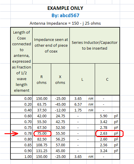
SKETCH 1 of 3 : IMPEDANCE TRANSFORMATION BY A PIECE OF COAX 0 to 1/2 WAVELENGTH LENGTH

SHETCH 2 of 3: IMPEDANCE MATCHING / SWR IMPROVEMENT METHOD

This method uses the fact that a piece of transmission line (Coax) transforms the impedance of antenna connected to it. The value of impedance seen at other end of coax depends on length of piece of coax. The impedance transforms in a cyclic manner, returnig back equal to antenna impedance every 1/2 wavelength. At a particular length in between 0 and 1/2 wavelength, the Resistance transforms to exactly the impedance of coax/receiver, and reactive component transforms from capacitive to inductive. At this point if a capacitor of appropriate value is inserted to cancel the inductive component to zero, only resistive component remains which is equal to system impedance, and stays same along remaining entire length of feed coax.
..
SHETCH 3 of 3: GRAPHICAL REPRESENTATION - IMPEDANCE TRANSFORMATION ALONG LENGTH OF COAX

Impedance as seen through a length of transmission line
A perfect impedance match by a piece of coax and a capacitor
with this you can make hot cocoa? wooo hooo!
The best plan I have heard all week :)
Dave
"Coco" mentioned here has nothing in common (except name) with the food items coco & drink "hot cocoa"
CoCo is nick name/short form of "Coaxial Collinear Antenna", made of multiple ? λ long (electrical length) pieces of Coaxial Cable. The core & shield of adjuscent pieces are cross connected at every joint.
My post relates to impedance matching of antenna with receiver, thereby lowering its SWR, and improving its performance
Trying to understand how the matching method is applied practically. You state to use no test equipment, also the antenna impedance will be unknown in the general case.
The coax segment length is determined by trial and error (best S meter indication?). How about the capacitor value?
You should have just said that for a start instead of using uncommon terms
I have built a few coaxial co-linears over the years for 430 MHz and 1296 MHz ham bands.
They work OK. just don't try too many segments as the law of diminishing returns comes into play
here's one on my www site that I that I used to play with ....
http://www.sydneystormcity.com/microwave.htm
cheers
Dave
Hi Dave!
Thanks for sharing the link for drawing of your 2400 MHz Coaxial Collinear antenna.
Nice design. Will give it a try.
The problem I was trying to solve pertains to DIY CoCo made using coaxial cable RG6 vastly used by TV & Satellite installations. This cable and its fittings are low-cost & commonly available. This cable has an Aluminum foil & braid, and soldering is not possible. The method used is "push-pin", i.e. the core of a piece is joined to braid of next piece by pushing the core wire between outer jacket & braid of the next piece. Hence the name push-pin method.
This originates from the relatively new hobby of ADS-B flight tracking using (or misusing) a DVB-T USB Receiver. This receiver is very cheap, S25 if purchased from USA, S10 if purchased from China. This was originally intended for receiving Digital Video Broadcast (Terrestrial) for European System. It has two chips, RTL2832 + R820T. Some wise guys discovered its tuner chip R820T has a wide frequency range (24 – 1766 MHz, can be improved to ~13 – 1864 MHz with experimental drivers), and can be used as Software Defined Radio (SDR). He wrote a driver software, and some others wrote Receiver Software, most popular being SDR# (SDR Sharp). Also one group wrote a software which tuned this tuner to 1090 MHz, and had a decoder to decode position, elevation, speed etc signals transmitted by aircrafts. RTL1090 by jetvison.de for Windows, and dump1090 for Linux/Raspberry Pi. another set of software also sprang which plotted the position data output from these receiver-dfecoder softwares on Google map in a web browser, making a live display of aircrafts flying around the receiver/antenna upto maximum distance of 500 km / 250 nautical miles.
The above development made this hobby tremedously popular, as it required less than S50 investment. Since most hobbyists wanted a low cost antenna as well, the Coaxial Collinear made of RG6 Coax, using push-pin method became very popular. However, as I have mentiond in my first post, majority of hobbyist ended in CoCo with poor performance, a result of lack of expertise, understanding, using cheap quality stuff etc.
My post was specifically for ADS-B hobbyist scenario.
One more problem with these hobbyist is they thing "bigger is better", so they try to make CoCo with 8 to 24 number of elements! they dont understand that every doubling the number of elements increases gain by 3 dB. So to increas gain by 6 dB, the number of elements have to be doubled twice, i.e. 4 times. As you said, the law of diminishing returns applies here.
Regards
abcd
[SIZE=4]Photos of ADS-B Equipment & Setup mentioned in my last post
System Setup with Satellite in-Line Amplifier

The screenshot below shows how the position signals from aircrafts (within 450 km / 250 nautical miles of receiver) are decoded & plotted on google map by software "dump1090" (Raspberry Pi /Linux) or softwares "RTL1090" + "Virtual Radar Server" (Windows).

You are right about antenna impedance, best S-meter indication & adjusting the series capacitor also by trial & error.
The starting point is Antenna Impedance. Once antenna Resistance & Reactance are known accurately, the length of coax piece & value of series capacitor can be calculated accurately.
The average DIY hobbyist does not have any fancy test equipment, hence this basic information is missing. In this case a typical value for the type of antenna used, is to be determined & used and the values of coax length & series capacitor determined. Then starts the trial & error by using different coax pieces (calculated length of coax piece ± few mm) . With each length of coax, again use different values of capacitor (calculated value of capacitor ± few steps of 0.5 pF). Alternatively a variable trimmer capacitor of suitable value can also be used.
I also dont have test equipment except an analog multimeter (S10 value ). I used a simulation program to find out typical value of a 4-element Coaxial Collinear antenna for 1090 MHz (for ADS-B). The element length with RG6 Coax (VF=0.83) worked out 114 mm. The simulation gave me the Resistance & Reactance values of the simulated antenna, which I used as "tyical" value. I went one step ahead and run a sweep of element length varying from 110 mm to 120 mm to get a range of values for antenna impedance. now instead of calculating coax length & capacitor for only one typical value for 114 mm, I calculated for upper (120 mm), lower (110 mm) & designed (114 mm) element lengths using formula given in my last post (or easier by using Smith's Chart). Below are the results, which give the range: Coax piece 0.65 to 0.85 of 1/2 wavelength, Series Capacitor 1 to 1.5 pF.
STEP-1of 2:
DETERMINATION OF 4-ELEMENT 1090 MHZ COAXIAL COLLINEAR ANTENNA's IMPEDANCE (TYPICAL VALUES) BY SIMULATION
STEP-2 of 2:
CALCULATION OF LENGTH OF MATCHING COAX PIECE & VALUE OF SERIES CAPACITOR
| ANTENNA IMPEDANCE | MATCHING COAX LENGTH |
SERIES CAPACITOR |
| UPPER VALUE (256+j80 ohms) | 96.5 mm 0.85 of 1/2 wavelength |
1.5 pF |
| TYPICAL VALUE (175-j172 ohms) | 90 mm 0.79 of 1/2 wavelength |
1.1 pF |
| LOWER VALUE (32-j85 ohms) | 74 mm 0.65 of 1/2 wavelength |
1.0 pF |
.
no probs .... 1296 MHz NOT 2400MHz :)
just scale measurements if you are wanting to use on 2400MHz
yeah last thing you want to use if RG6 that's just making life difficult for yourself
use RG8 or RG213 :)
cheers
Dave
COCO PERFORMANCE IMPROVING 相关文章:
- Improving radiation performance by using a mutual coupled antenna
- Ultra High Performance Morion 10 MHz OCXO
- Which PC performance are necessary for the electromagnetic simulations?
- Single Side-band Performance
- How to verify BER performance of my RF receiver?
- improvement in antenna performance for wban (wireless body area network)
