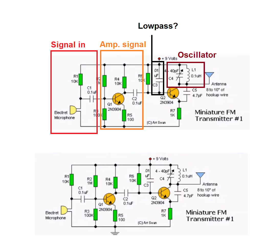
Can you explain the end part of this FM circuit?

What does the C5 capacitor do?
I'm guessing R6, Q2 and R7 is just an amplifier that multiplies the mic current with the oscillating collector current?
If someone can answer those two questions I'd be very happy :)
At the oscillating frequency Q2 is a common base amplifier. The feed back to get it oscillating is provided by C5. It may work with out C5 if the parasitic capacitance of the device is high enough.
R6 provides the base current for Q2 and R7 limits the collector/emitter current to the required value; inthis case it will be a little more than 8mA.
Q1 and associated componets amplify the microphone output and the output of Q1 modulates the base current of Q2. This cuses the operating point and parasitic cpaitances in Q2 to change and so changes both the oscillating frequency and to a lesser extent the output power.
In all it is a very crude FM transmitter.
The circuit is not an amplifier, and is just a common base Colpitts oscillator with an antenna attached at the output.
C5 is the feedback capacitor, and C3 is the base decoupling capacitor.
C3 has low reactance at oscillation frequency (RF), and high reactance at modulation frequency (AF).
This is a poor design, and if you touch the antenna, the oscillation frequency would change inevitable.
So as not ot confuse Addez, I don't think we are in disagreement, it is a matter of how it has described. Q2 is the common base sustaning amplifer for the oscillator.
We are both in agreement that it is not a good design technically.
Hi
Q2 is the RF oscillator for FM which is used in Common base arrangement . So every CB amplifier needs a bypass capacitor to short circuit the gate instead of AC signal . ( of course there are some expects too ! )
So In equivalent AC circuit , C3 is bypassing the gate ! simply !
C5 is providing positive feedback to make the circuit unstable ! in fact it shifts poles of the circuit into the unstable section of the S plan.
it's value can be about 0.5C4 ( by a rule of thumb ) .
R6 is DC base bias of the Q2 ( as CB amplifier which amplifying RF cycles because the circuit is tuned for RF ) ( an RF amplifier can be changed into an RF oscillator simply ! )
A question , are you sure you're familiar with CB amplifier ? if no i highly recommend you to study about it .
Best Wishes + Good luck
Goldsmith
- Simulating digital part in ADE Cadence Virtuoso
- Difference in the reactive part between loadpull simulation and large signal sparams
- How can the Reactive part of Zopt absorbed into the drain line in a DA
- Waveguide Part Identification Help
- Partial/Defected Ground Patch antenna simulation
- Anyone notice, all the parts are becoming discontinued?
