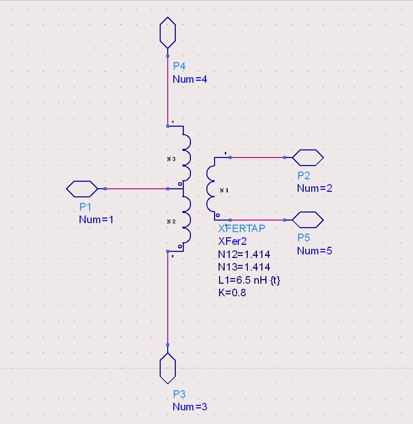
Planar Center Tapped Transformer Design
I would like to design a planar center tapped trasnformer working the the ISM Band (2.4-2.48GHz). I was planning to realize it over a FR4 board 1.6mm thickness. I was thinking to implement it using a Frlan transformer layout in order to maximize the Km index. There′s just a problem which is the technology limit. I can fabricate maximum 0.1-0.2 mm windings width over the FR4 layer. I have read some general on chip transformer guideline (like Monolithic Transformers for Silicon RF IC Design ) but all the implementations are on microscale. My doubt is if it is possible to achieve the same performances using an FR4 board 1.6mm thick and windings with space in the order of 0.1/0.2 mm.
Any suggestions? Design procedures and steps?

Thank you so much.
FR4 is not so good at 2.4GHz because the permittivity varies significantly but it's not impossible. I think it will become quite complicate to realize such transformer at this frequency with this parameters. I don't know where are you from but there exists discrete transformers for this frequency. I saw you have ADS, than you can draw and em-simulate your design. Maybe also take some process variation into account.
FR4 will be very lossy especially in transformer structures.0.1/0.2mm gap will also not be very consistant due to high manufacturing tolerances.
Yes FR4 will be lossy, but OK for experimentation, why not go to thinner FR4? (0.4mm) and have a few layers, e.g. 3: pri,sec,pri, or 5, to increase the coupling and keep stray radiation down?
You will also decrease the self resonance frequency of the structure caused by capacitive coupling in this way. And the dielectrics have significant different thicknesses. In my opinion, it's better to take a discrete transformer.
I simulated a simply pcb transformer at 2.4GHz, first of all, your inductance values are quite small for a pcb transformer. And second, the coupling factor is also lower, even with 0.1mm spacing.
Ok, thank you for the useful informations. I have tried to simulate with the em simulation but I couldn′t get good results and that′s the reason why I don′t know how to realize a transformer with this kind of material and technology limits. I have 4 questions:
1. why is the self inductance to low at that frequency? I have simulated the S-transformer parameters with ADS and I got good results with that value.
2. How about discrete components? I have try to look for a center tapped transformer working at this frequency but I could find a suitable one. Almost all of them are working between 100KHz and 1.5GHz. I have found some baluns and have attached the PDF file and http://www.farnell.com/datasheets/1678468.pdf . Can I use them? I cannot see the schematic in almost all of them and I′m wonder if it can be used as a center tapped transformer.
3. Is there one other way to simulate the transformer instead of using ADS ?
4. I′m actually using this transformer in an Hybrid Junction and the target is maximize the isolation between TX and RX for wide bandwidth (80MHz-100MHz) at 2.4GHz. Are there any kind of structure that allow that. I have already try to use some bidirectional couplers, four branches couplers , rat race but all of them exhibit less isolation compare to the transformer.
- How power is conserved using tapped capacitor circuit ?
- [FEKO] How can I draw a planar circular spiral with rectangular cross section?
- Re: planar coil magnetic field strength calculation
- planar coil magnetic field strength calculation
- Coplanar waveguide to Microstrip transition
- planar inductor or capacitor
