Re: simple 15mhz crystal filter how to?
Its a solution to a problem you may not have.
I would just buy a standard commercial ceramic or crystal bandpass filter, they are not expensive and it will behave much better than something home made.
They are just a three terminal device, input, ground, and output.
There are a huge range of operating frequencies from below 500 Khz to above 100 Mhz and a wide selection of bandwidths are available, the impedances are well defined and they are very easy to use.

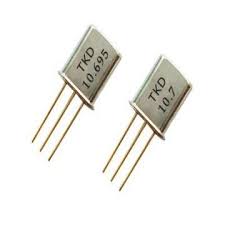
Yes, I have seen these, and in fact I have one of these for 10.7MHz with a +\-3KHz bandwidth. These filters would be excellent as they offer more bandwidth than a single crystal. In fact I was thinking of switching between them. When fine resolution is needed (at slow sweep rates) the single crystal may be used. Then some of these crystal filters you propose may be used for decreasing resolution and achieve faster sweep rates when you need it.
The 15MHz frequency is a bit non-standard, but It wouldn't be difficult to find one.
However, for the time being, I will stick with the homebrew solution, as a prove of what can be done in simple easy to find homebrew components.
BTW, I see no reason to use a transformer before the crystal, or to change the filter. It works well as it is, as shown on the FFT and no tuning is needed. The +\-1% capacitor may be hard for one to find though, but +\-5% NPO could be used if it is close to it's nominal value. A few of these would have to be tested.
I really try to find out how to proceed with the discrete components log amplifier, as pointed to another thread, or if I can just hook up a simple envelope detector and get away with the complexity...
I have not seen a 15 Mhz crystal filter, but 14 Mhz seems to be available in 2.2 Khz bandwidth, and up to twelve poles !
http://www.golledge.com/docs/product...tl/gmcfgen.htm
14MHz is not good. It means that the split-range of the SA will be in the 20m ham band. We need to monitor this band and we can't that way.
I think if one connects two or more 15MHz parallel crystals he could achieve a greater bandwidth. How much, will depend on the crystal characteristics. It is done in the so called super vxo.
Another simpler way could be this http://5.55.108.123/narrowxtalfilter...XtalFilter.htm
This is actually used in the Tektronix 491.
However, I am not sure why they have used a negative voltage to bias the diode? Do I have to reverse the diode polarity if I use a positive one?
It would be interesting to try.
