What would be AC load line if AC is blocked? (biasing resistors not loaded with AC)
what would be equivalent circuit? R1,R2,Rc,Re only loaded by DC.
http://ecetutorials.com/analog-elect...ermal-runaway/
Should i consider something like Rc=50 Ohm?
AC equivalent circuit of BJT/FET amplifier is usually given like that:
(image from http://ecetutorials.com/analog-elect...ermal-runaway/ )
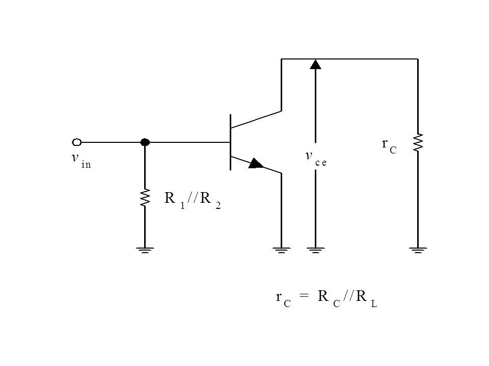
But at high frequencies, biasing is done through thin lines with quarterwave stubs,
so biasing resistors not loaded by AC signal, and they disappear from AC equivalent circuit:

(image from http://radioaficionsdr.es.tl/Circuit...Microstrip.htm )
The only resistance is left is Rload and Rsource (i think).
In all examples AC load line calculated for Rcollector||Rload. So only Rload left for AC circuit analysis?
I know how to calculate DC load line.
Now i am trying to calculate AC load line, but do not know what AC equivalent circuit would be. Should i consider only one resistance Rload=50 Ohm?
For VCC of 8v and Q point
Vce=4v
Ic=15ma
my DC load line goes through Vcc=8v, IcQ=30mA
Then assuming Rl=50 Ohm (guess it is wrong, because matching network is not assumed)
Vc=Vce+Ic*50 = 4.75 v
Ic= Ic+Vce/50= 175 mA
Yes, as far as if you ignore incompleteness of quarterwave stubs
Thank for your reply! How about matching network?
For example, i decided to use Zload= (70 +j*4) Ohm. With 50 Ohm load.
So i transform 50 Ohm to Zload using stubs/lines/inductance/etc.
Although load is 50 Ohm, it is transformed to (70 +j*4) Ohm
As i understand, it is enough to use real part of final impedance (70 Ohm), that looks into transistor's collector. Not sure if +j*4 complex part can be used somehow.
AC load impedance is (70 +j*4) Ohm.
Wrong.
Transistor's collector looks AC load impedance is (70 +j*4) Ohm.
If Zload is real number, locus of (Vload, Iload) forms line which passes DC Operation Point, (Vload_DC, Iload_DC).
If Zload is complex number, locus of (Vload, Iload) forms elliptic which never passes DC Operation Point.
Try to plot dynamic locus of (Vload, Iload), using following two methods.
(1) Transient Analysis.
This locus starts from DC Operation Point and forms elliptic after long time.
(2) Large Signal Periodic Steady State Analysis such as Harmonic-Balance or Shooting-Newton.
This locus is elliptic and never passes DC Operation Point.
Thank you! I see it now.
I have additional question about oscillator:
when i draw IV curve for oscillator, it looks almost like circle, also pretty distorted.
Can i make some conclusions by looking at IV dynamic locus shape?
I found something here:
http://www2.ece.ohio-state.edu/~robl...g_05725592.pdf
by feeding transistor with sine signal i obtained elliptic curve (very slim, almost like line).
but oscillator have very "distorted huge circle" IV curve...
If someone interested in drawing AC load line, i tried it in SpeqMath and superimposed on Transient analysis curve (biasing as in S53MV's bfp420 VCO, but AC is blocked for biasing resistors):
QpointVce=VceQpointVce = 4

QpointIc=IcQpointIc = 0.015

QpointIc=0.014QpointIc = 0.014


dcLoadLineVce=VccdcLoadLineVce = 8

dcLoadLineIc=Vcc/(Rc+R_e) 'AdcLoadLineIc = 0.03

acLoadLineVce=QpointVce+QpointIc*50acLoadLineVce = 4.7

acLoadLineIc= QpointIc+Vce/50acLoadLineIc = 0.094


x1=dcLoadLineVce;
y1=0;

x2=0;
y2=dcLoadLineIc;

slope=(y2-y1)/(x2-x1)slope = -3.75e-3

dcLoadLineIcAns = 0.03
dcLoadLineVceAns = 8

m=-dcLoadLineIc/dcLoadLineVcem = -3.75e-3

dcLoadLineVceAns = 8


' y-y1=m(x-x1)
' y = m*(x-dcLoadLineVce)

f(x)=m*(x-dcLoadLineVce)Function f(x) is defined

Plot(f(x))Plot done

acLoadLineIcAns = 0.094
acLoadLineVceAns = 4.7

m2=-acLoadLineIc/acLoadLineVcem2 = -0.02
f2(x)=m2*(x-acLoadLineVce)Function f2(x) is defined

Plot(f2(x))Plot done
I think it is correct, but not sure.
I can not understand what you want to mean at all.
What analysis do you use ?
If you use Transient Analysis, (Vload, Iload) include higher harmonics. Here you can not use constant value reactance such as Zload=70+j*4.
See https://www.edaboard.com/thread202948.html#4
On the other hand, you can plot (Vload, Iload) locus regarding single frequency, if you use Large Signal Steady State Analsis.
Here you can use constant value reactance such as Zload=70+j*4.
Show me your (Vload, Iload) locus.
What simulator do you use ?
You can plot (Vload, Iload) locus very easily, if you use Keysight ADS, Keysight GoldenGate, Synopsys HspiceRF, Mentor eldoRF, AWR MicrowaveOffice, Ansoft Designer, Nexxim, Cadence Spectre, etc.