Please help with the source of heavy interference found in signal of GPS front end
时间:04-04
整理:3721RD
点击:
I recently designed a GPS front end and I found lots of interference in the collected data. Front end contains SAW filter with central frequency 1575.42 MHz, BGA2001 LNA, MAX2112 mixer, MAX19505 ADC converter, Spartan 6 FPGA and EZ-USB FX2 USB micro-controller. The clocks of MAX2112, MAX19505 and FPGA are all from one clock synthesizer LMK03033 and they are all 26 MHz. The clock of the FX2 USB micro-controller is 24MHz. The local clock of MAX2112 is generated based on the multiplication of 26 MHz. The data from ADC is written into a FIFO inside the FPGA with 26 MHz clock and read out by FX2 USB with 48 MHz IFCLK.
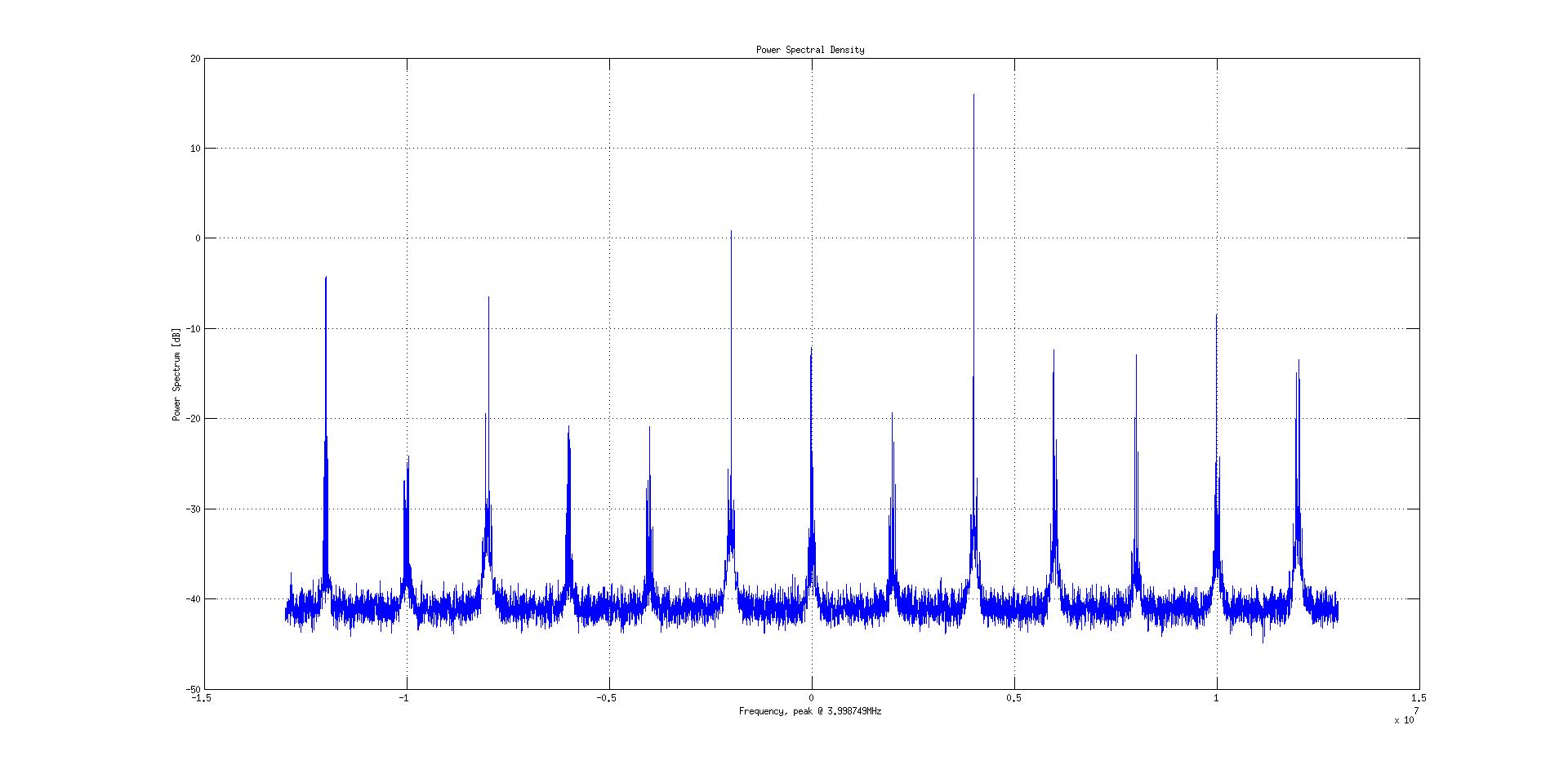
I then input a single tone of 1579.42MHz and the expected intermediate frequency is then 4 MHz. The analysis results of the collected data shows that while I can see the expected 4 MHz intermediate frequency I can also see lots of interference which all seem have about 2 MHz distance, for example, 6 MHz, 8 MHz and -8MHz, -6 MHz, -4 MHz, -2 MHz ... 2 MHz, etc although they have lower power than the expected 4 MHz intermediate frequency. As you can see in the attached image.
Did anybody see this kind of interference in your test? What are they and where do they come from? How to avoid them in the front end design?
Thanks.

It looks like a mistake in digital domain rather than an interference problem. Do you see anything in the spectrum when you do NOT apply any signal(terminate the input with 50ohm if possible)? You can also observe what happens when you shift the input frequency 1 MHz.
You can probe the signal before it goes into the digital blocks. You must have a check point there before the digital blocks! Probe there and observe with a spectrum analyzer to see whether a real interference is exist or they are generated in digital blocks in a way.
