microstrip antenna design - help
The frequncy is 5.8Ghz
thanks in advance for you help
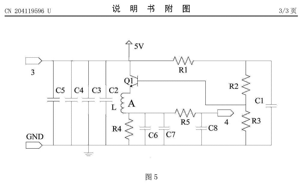
Interesting indeed. The wiggly line corresponds to inductor L1 on schematic. Is the transistor just a voltage regulator or there is more to it? We likely learn more if we know where these designs came from.
This design is similar to a Chinese record
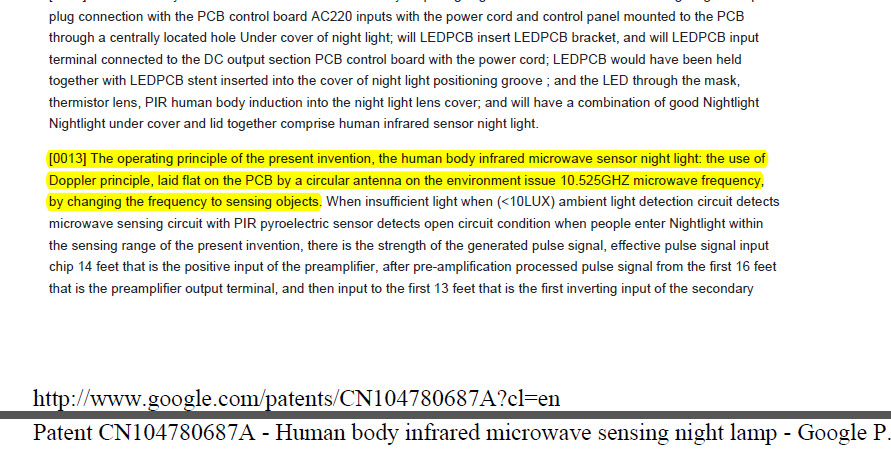
http://www.google.com/patents/CN204119596U?cl=en

So it is not just an antenna, it is energy saving LED power supply circuit. L1 is an antenna to pick up energy from 5.8 GHz radio sources. Efficiency of this antenna will be maximized when it is resonant at operating frequency. Also it's aperture should be maximized. How do you know it is specifically designed for 5.8GHz? What these boards are made for?


I looked for some more articles about this patent and found the following articles
In one the frequency is 5.8GHz and the other one is 10.52Ghz
I suppose it depend on the operating distance
http://www.google.com/patents/CN104780687A?cl=en
http://www.google.com/patents/CN203434265U?cl=en
Do you have any idea how to design the pcb layout according to the frequency and the distance operation ?

Yes I can. According to the frequency. Just as I said earlier antenna has to be resonant, actually the whole circuit has to be resonant. To maximize energy pick-up efficiency you usually want to maximize aperture - the area the antenna takes, but must remain resonant. And it should be matched - by adjusting components after the antenna so the energy travels further to the load. The rest of the circuit (Transistor) is power source an it will drive the LED's even without RF. When RF energy is presented it's efficiency improves. The patents likely describe the details. Only it is difficult to comprehend the patents - the English could be better.
: )
One of these, doppler sensor.

Yes, But
Our design is to integrate the Doppler antenna on one board with the driver and a PIC microcontroller
That's why we can not use a standard board as in the picture you have sent, and we have to design the Doppler antenna pcb layout by our self
microstrip antenna design 相关文章:
