Poynting Vector of a Loop Antenna
时间:04-04
整理:3721RD
点击:
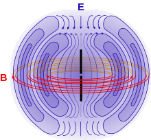
So I came across the following image (from Wikipedia)
where the electric and magnetic field lines are depicted for a dipole antenna. From the field lines, it is possible to determine the direction of the poynting vector, using the right-hand rule. If all possible combinations of poynting vectors are considered, an entire plane is described, perpendicular to the antenna axis.
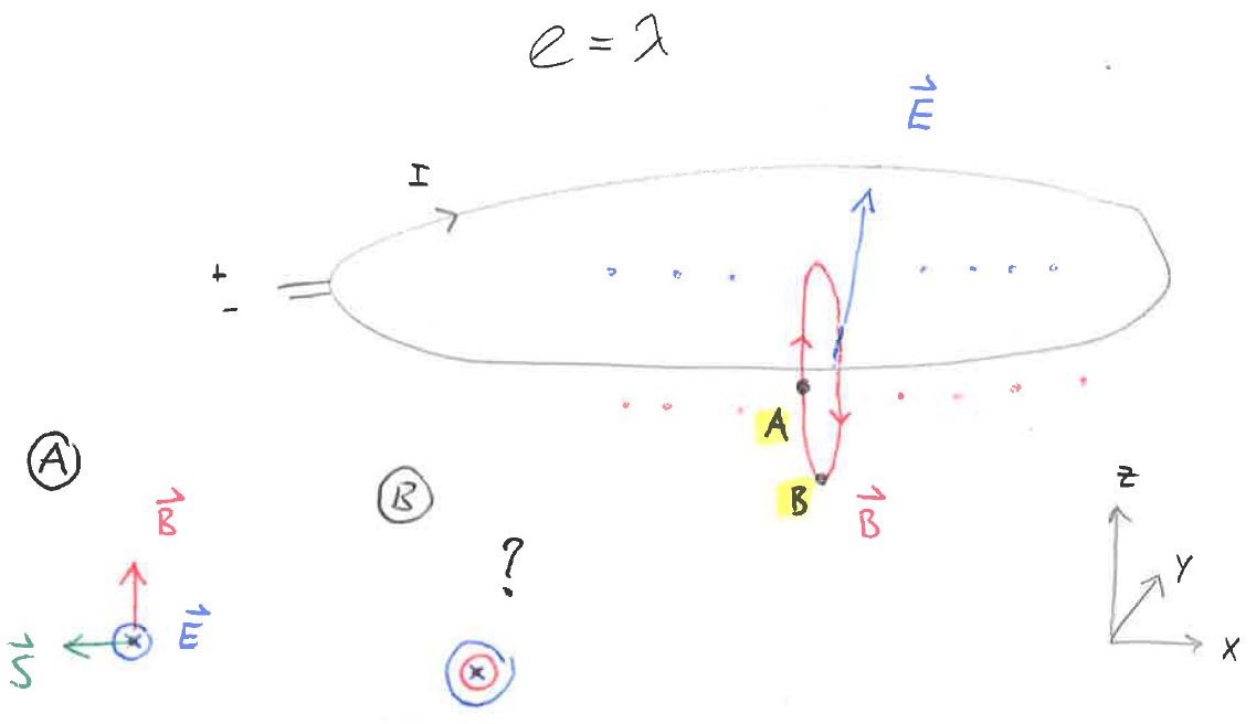
I was wondering if there is an analogous consideration for loop antennas. I came up with the following sketch
whereby the loop is situated in the XY plane. I drew in one possible electric and magnetic field line at a certain time instance. If the "A" is considered and the right-hand rule is applied, the poynting vector lies on the X-axis. If however point "B" is considered, the magnetic field and electric field are opposite to each other and the poynting vector can't be resolved.
1) Is my assumption of the field lines possible/correct?
2) How to determine the poynting vector in the case of the loop antenna?
3) How about near/far field effects; under which circumstances are such considerations valid? Is the dipole an exceptional example that "always" works?
Constructive and elaborated answers are appreciated.
where the electric and magnetic field lines are depicted for a dipole antenna. From the field lines, it is possible to determine the direction of the poynting vector, using the right-hand rule. If all possible combinations of poynting vectors are considered, an entire plane is described, perpendicular to the antenna axis.
I was wondering if there is an analogous consideration for loop antennas. I came up with the following sketch
whereby the loop is situated in the XY plane. I drew in one possible electric and magnetic field line at a certain time instance. If the "A" is considered and the right-hand rule is applied, the poynting vector lies on the X-axis. If however point "B" is considered, the magnetic field and electric field are opposite to each other and the poynting vector can't be resolved.
1) Is my assumption of the field lines possible/correct?
2) How to determine the poynting vector in the case of the loop antenna?
3) How about near/far field effects; under which circumstances are such considerations valid? Is the dipole an exceptional example that "always" works?
Constructive and elaborated answers are appreciated.
Is it a resonant loop (circumference= 1 lambda)? So current distribution cannot be regarded as constant. Your assumption of the fields may be incorrect. In fact the averaged Poynting vector lies on Z axis! Tell us if you mean a small loop antenna.
You will find that a thin wire dipole has a pattern pretty much the same as a thin wire loop, except the electric and magnetic fields are interchanged. The Poynting vector distribution is essentially unchanged. These two antennas have the same radiation pattern.