Frequency multiplier HCF4046 synchrnized with mains frequency (50Hz)
I would like to do a frequency multiplier synchronized to the frequency of the mains (i.e. 50Hz)
I am using an old(but gold) HCF4046, I have read several data sheets, application notes but I am still stuck.
Here are the parameter
R1 = 10kOhm
C1 = 2.2nF
Vcc = 5V
-Vcc = -5V
so the central frequency is around 20kHz
I am using a divider between VCOout - COMPARATORin, a HEF4040, for now just to divide by 256.
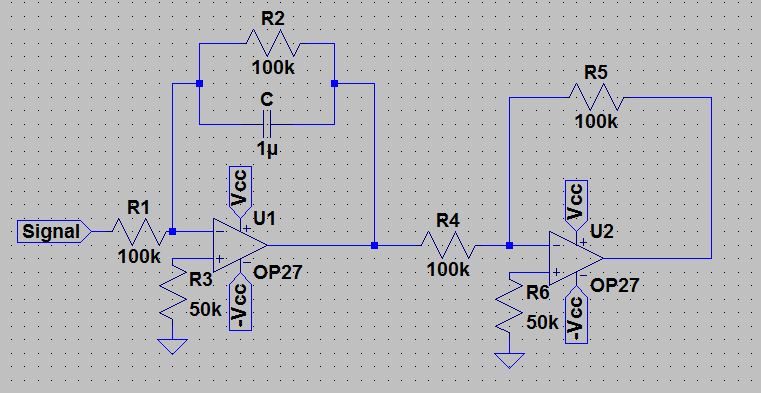
I am using Phase Comparator 2 and between PhaseCompIIout and VCOin I have an active loop filter:

The problem is that no matter the filter I am using (tried also a lead-lag passive filter) the output frequency is not stable at 12800Hz but it somehow oscillates and the most surprising fact is that with the passive filter it had an oscillation of around +-2Hz around 12800Hz while with the active filter it is even worse.
It's a long time and finally I decided to ask for some help, have you any suggestion/hints?
Without telling the passive filter topology and dimensioning, the comparison doesn't mean much. In any case I suggest a PLL phase margin analysis.
I presume, with "passive lead-lag" you refer to the RRC filter suggested in the 4046 datasheet? It should basically work, question is if you found the right component values. It must be dimensioned for the 50Hz PFD frequency, which is rather low.
Yes, I meant the RRC filter.
When you say "It must be dimensioned for the 50Hz PFD frequency" can you give me some kind of reference? Maybe I just put the wrong values in the LPF.
First you need to get the VCO working properly. This requires two appropriate resistors, one from pin 11 to Vss, and one from pin 12 to Vss.
Fit a potentiometer to pin 9 so you can adjust the VCO input voltage all the way from Vss to Vdd.
Monitor the output frequency so it covers a suitable range with 12.8 Khz in the middle.
Maybe +/-10% (its not critical) say11.5 Khz to 14.1 Khz for example.
Just so that the VCO can work properly at 12.8 Khz and allow enough range so it can stay in lock if things slowly change.
Nearest standard commonly available resistor values will be fine.
You need to get all this working first, before you try to close the loop. I suspect that not having any R2 fitted will be your problem.
Try this first and let us know how you get on...
