Q-multiplier as a front end BPF?
Can a Q-multiplier be used as a front end BPF in a receiver?
I am talking about a wider bandwidth (200KHz or so) not a narrow one, like a regenerative detector.
Any ideas/circuits to try for 40m?
I would like to see if I can build a BPF frontend filter for 40m without coils with such a multiplier.
To create a rolloff curve with a capacitor, there also needs to be ohmic resistance nearby to create an RC time constant. Ohmic resistance decreases Q, normally. You can add RC stages to make the rolloff curve more acute, but you probably lose as much as you gain.
Although inductors are troublesome to work with, they are a component that achieves remarkable things, especially in combination with a capacitor, and with minimum resistance to hamper their behavior. That is a great method to multiply Q.
The potential of inductors seems so large that sometimes I get the idea that the world (electronics world, that is) belongs to those who are experienced with inductors, constructing them, using them in small signal applications, motors, power conversion, etc.
I have seen some regenerative BPFs for audio that can do a great job as narrow filters using RC. I thought that maybe this can be done on HF too, but with a bit more relaxed regeneration, to allow for lower Q and spread the bandpass throughout the whole HF band (~200KHz).
Consider that a receiver input stage should fulfill also requirements like blocking of strong off-band signals and high signal-to-noise ratio. A LC filter can usually achieve it better than an active RC filter.
That is exactly my purpose, to reject strong out of band signals. With my simple broadband transistor amplifier, there is intermodulation and strong broadcast signals can be heard inside the radio amateur bands.
Without LC filters, this could be achieved by high dynamic range preamplifiers, but I am trying to find out if this can be done with regeneration as well.
To some extent, the regeneration level is controlled by the strength being received so a passive solution is better. You have already witnessed what happens when an audio regenerative filter breaks into oscillation.
The nature of a regenerative filter is to peak at one frequency, I doubt you could achieve a flat passband over the 200KHz or so you need and still have sharp skirt edges. Besides, a regenerative filter at 7MHz would still need inductors so why not use them to make an LC filter instead.
Brian.
The last audio filter from this thread https://www.edaboard.com/thread36303...ml#post1555568 we were discussing, worked nice for me, but there is some tweaking needed and I do not know yet how to cope with it.
However I understand the issues when regeneration used as wide BPF on RF, so I guess the only coil-less solution would be to use a broadband high dynamic range RF preamp (they can be made coil-less).
Yes, but they inevitably achieve high dynamic range by running at high current and low gain, looking at is simply, the strong signals are 'diluted' by the high background power in the stage. You need to use a power transistor running at maybe 100mA+ to do what you want, it will work but is very inefficient.
I have to add that overload in a single stage receiver (assuming it is the one previously described) is unusual. I suspect it has something to do with the characteristics of the resonator you are using, it is after all designed to have a wide bandwidth and also to be impedance matched on both sides. It is possible the strong signals are not overloading the receiver but pulling it into tune with them.
Brian.
If this was the case, I should listen to these strong out of band broadcasting signals and not both the strong and the weak CW signals, shouldn't I?
It is like to expect from a single broadband stage bc549c amplifier not to intermodulate.
Maybe this will give you a hint of what's happenning. Even with the narrow CW filter on, these strong BC voice signals are still comming in.
The point I was making is your tuning element is a broadband filter so although wrapping an amplifier and feedback around it will make it peak at one frequency, it is nevertheless designed to pass signals over a wider band.
Am I right in guessing the filter is centered on 7.02MHz as used in the audio stages of satellite TV receivers?
Brian.
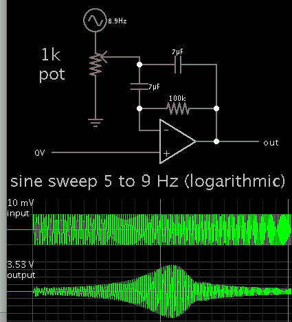
I modified a filter schematic from this tutorial by TI:
http://www.ti.com/lit/an/sloa093/sloa093.pdf
The slow frequency demonstrates it can be done without a large inductor.

I"m not sure about its operating principle. It might be partly regeneration, partly gyrator (active inductor).
The amplifier does not necessarily have to be an op amp. There ought to be a way to distill it down to a simpler amplifier made from transistors (maybe a differential amplifier).
The resonator is a 7.16MHz one and I pull it down to about 7.004MHz-7.080MHz or so.
btw ceramic resonators for ham bands other than 80m are hard to find, if you know any source please let me know. I have managed to find for 40m so there is no need for this band. 30m would be great!
hm... interesting.
However as Brian said, there is a terrible passband variation! It is expected from any positive feedback system I guess.
