Power Amplifier Design 1dB Compression Point
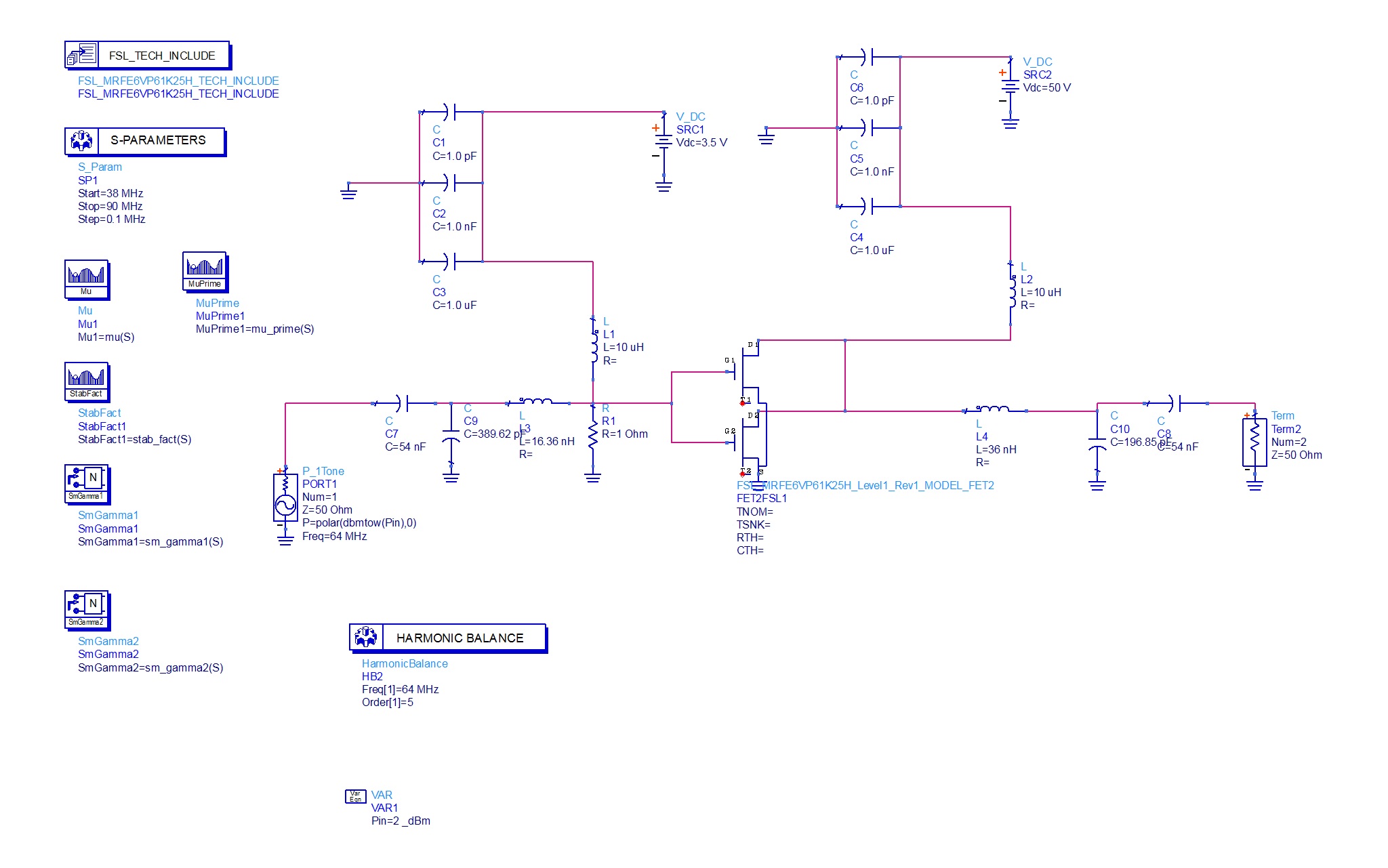
I need to design a power amplifier at 64 MHz. The Freescale device (MRFE6VP61K25H) which I am using is capable of handling 1.25 kW of power.
I am attaching my design and results.
However, when I simulate in ADS for 1dB compression point, the maximum output power I get is 58 dBm.
I am unable to understand what is the limiting factor is getting the maximum power.
Please suggest solutions.


1. That part is meant to be used in a push-pull configuration.
2. It's meant to be used in class AB or C, which means that small signal matching is not going to get you the optimal output power.
3. How did you choose your gate bias voltage?
4. Is this, by chance, for MRI applications?
Fortunately the MRFE6VP61K25H is a popular part with the HAM radio community, and there are lots of useful designs (for various operating frequencies) floating around out there to learn from.
ftp://ftp2.rfham.com/rfham/SSPA6M.pdf
http://cache.freescale.com/files/rf_...TR_AMATEUR.pdf
http://www.w6pql.com/1_kw_2m_ldmos_amplifier.htm
Hi
I had chosen Vgs as 2.47 volt to operate in Class AB mode.
However, when I did not get sufficient output power from the device, I started increasing the Vgs.
Yes, this is for MRI application.
How do I go about large signal matching?
I would start by trying to reproduce results from a reference design before trying to tune to 64MHz.
ADS should have tools for doing this automatically, though I have no experience using them.
Also don't be surprised if the model itself is bad. I once tried to simulate an amp based on the ARF475 in SPICE and found that it couldn't give the specified performance, and eventually found that the model itself was at fault. Couldn't even replicate the DC bias curves in the datasheet...
