PCB trace antenna, loading coil question
I know I'll be giving up a lot of efficiency but it's the old story of space and manufacturing cost trade-off.
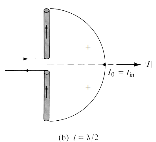
So I'm thinking that current is going to be strongest towards the foot of the antenna and voltage will be strongest at the tip. I will need to physically shorten the antenna and I was thinking of employing a loading coil in the form of a simple chip inductor.
Since I don't have to worry about wind load, I thought it would only make most sense to place the inductor near the tip of the antenna. Does that sound about right?
I'm putting my understanding of RF antenna field patterns to the test.
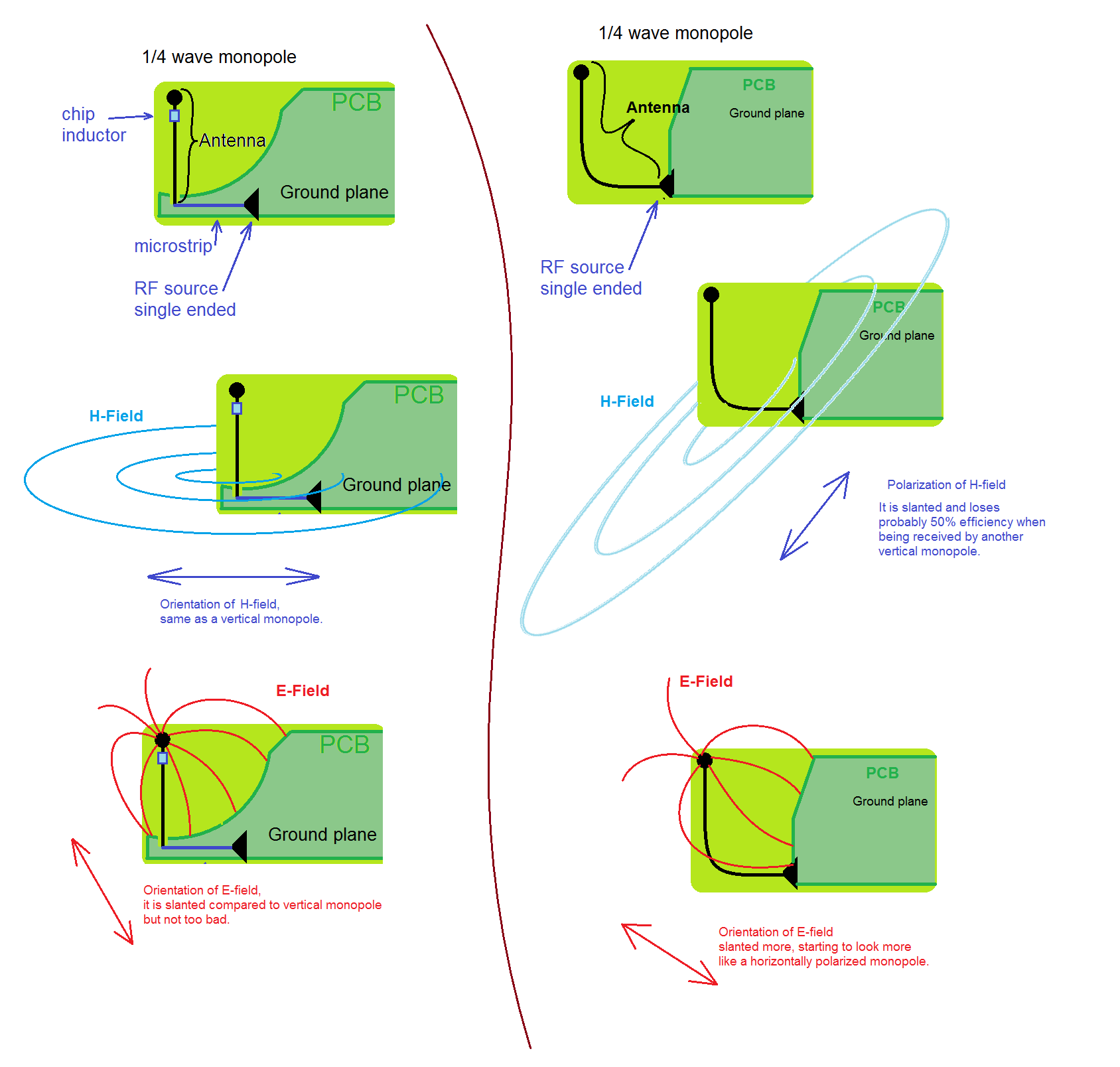
Attached are two different designs of PCB antennas. I can't afford simulation software, so these have been done in MS Paint :)
What do you think, is my understanding approximately correct?
If you read about current distribution in wire antennas, you'll see that the current drops to zero towards the tip. A coil near the tip has respectively very little effect. I think the name "loading coil" already suggests the position with maximal effect. You'll find multiband antennas with center coil, or helical antennas (a coil over the full length).
pgib8, your drawings are approximately correct. Topology on left hand will result in poor antenna with low resistance. Topology on right hand will result in much more efficient antenna, you should be able to get reasonable match if antenna element (shown as black line) will be close to quarter-wave length. You can think of it as a dipole composed of ground plane and horizontal section of your antenna, vertical section of it being capacitive load. If total length is still short of quarter wave length you can meander vertical section - same as adding loading coil. Pattern of resulting antenna will be similar to dipole oriented horizontally - corresponding to orientation shown on the picture. Correspondingly you will have 'holes' in directions of dipole ends. This is not very good. if you rotate your picture as a whole by 90 degrees so your dipole is oriented vertically you get quasi omnidirectional pattern and vertical polarization - much better.
I believe you, but are you sure? The loading coil for my intent isn't to match the antenna, that's something I can do at the feed point. I was thinking in my case, the loading coil facilitates the voltage peak at the end. Basically since I'm shortening the antenna below 1/4 wave, there needs to be a coil somewhere. I thought putting it at the tip makes more sense than putting it in the middle or bottom.
Interesting, although that's not what I thought. I thought the one on the left will be better. The magnetic field component is perfectly lined up with a vertical dipole. The electric field will be a little off but should still give a decent field.
My understanding of electromagnetic waves has recently changed, maybe that's what it is.
I now believe you can have "EM waves" with next to no magnetic but all electric, or respectively with next to no electric but all magnetic fields. Further I think that electric and magnetic don't have to line up like in pictures, with the 90 degree offset. Maybe it's even possible to have both magnetic and electric in the same plane.
A receiving antenna can do with just picking up one of these fields. Just a magnetic field will induce the current which will automatically also create the voltage (even if electric field wasn't there). Respectively just with the electric field, it will automatically create the current in the antenna too, even if magnetic field was missing. Thus I conclude the energy at the receiving antenna comes approximately 50% from E field and 50% from H field.
In my drawing I figured that the left side creates about 50%+25% = 70% while the right side creates about 25%+25% = 50%.
Maybe this is completely wrong, I definitely don't understand what makes up radiation resistance. I only know that more radiation resistance is good because that means more energy is radiated.