Inductive coupling power transmission


It is very general question to have details as S parameters have lot of details the point is what is important for you
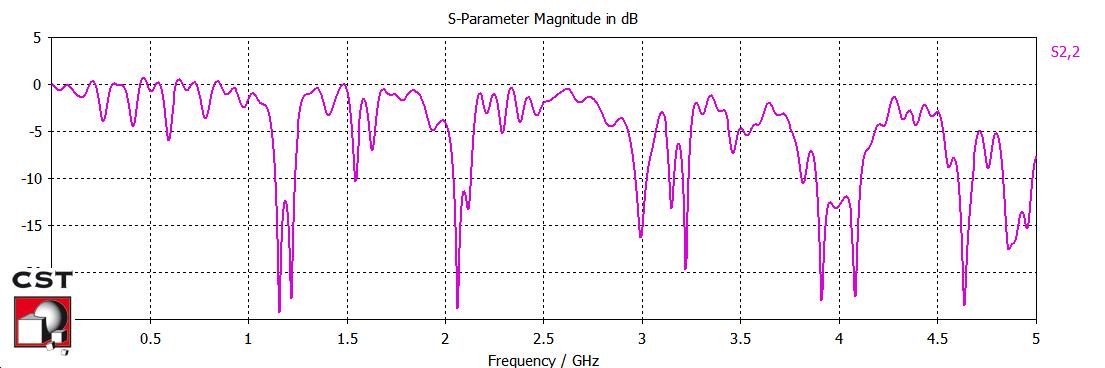
If we look as S11 and S22 the plots are not identical it means there is some directional element in the system like circulator.
If we have a look at S11 it clearly indicates a very powerful resonance mode around roughly 2.4 GHz indicated by sharp peak but there are other 4 resonance present as well in band of rougly 0.8 to 1.6 GHz
In the same way you can explain S22
A point to note is that usually at resonance we expect S11 to be around -40dB roughly.
now S21 and S12 which are transmission coefficient indicating that transmission is better at lower frequency but at your resonance it is not good.
I tried to explain but nothing could be explained as I do not know what is your goal
At first sight the s-parameters don't indicate that the measured two-port is serving a meaningful purpose. What is it? What do you expect?
Thank u for helping me. I wanna know the power transmission of those graph as I did the 2 layer inductive coupling on CST.
You can consider S2,1 power transmission of the design "as-is", without specific matching means.
What's the purpose of the design? Why are you plotting s parameters over this wide frequency range, does your design use a specific operation frequency?
S21 is measure of transmitted power from Port 1 to Port 2 but that should always be at a particular frequency or in a limited range of frequency your plot is upto 5GHz range with better transmission to 1GHz but still that range is not flat. So I will comment following
What is the frequency of interest at which you want to see the transmission
so narrow down your frequency range
for multi layer inductive coupling the power transmission the inductors is very low. what can be the solution to have a high power transmission?
Hi,
I'm not sure if I understand right,
If you want improve coupling on a PCB then ther are special ferritecores for that.
Klaus
Please start to ask meaningful questions.
- be descriptive. Tell about frequency, design purpose and other parameters necessary to understand your problem
- post a drawing or photo of the design under test
coupling Inductive transmission 相关文章:
- problem: coupling coefficient for two hairpin resonators
- Loose Coupling for a coaxial resonator
- Methods of decreasing the coupling between two closely placed antennas
- Re: Polynomial synthesis in coupling matrix technique
- Capacitive coupling between coaxial and coplanar circular coils
- Increasing stages coupling without increasing capacitance in TRX