Bandpass Filter Design at 64 MHz
I need to design a bandpass filter at 64 MHz with passband of 3 MHz and insertion loss of less than 0.5 dB.
I tried to design using lumped element LC topology. The simulation results are great but the very sensitive to value to the components.
Even a 0.1 nH of pF variation is causing the response to vary drastically.
Please suggest the approach I should take.
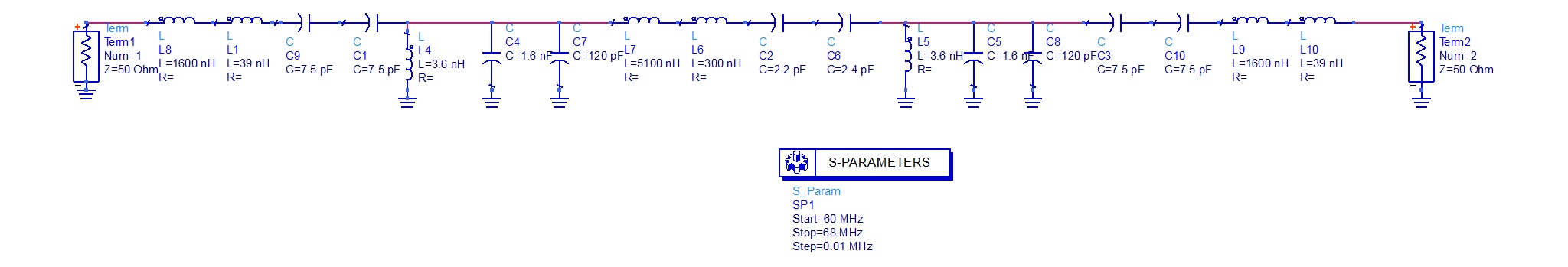
I am attaching my design and results for reference.

When an LC filter is designed to have less than 5% of BW from the central frequency, always get some critical influence of component values on the filter characteristic.
T type BPF has a better distribution of the loaded-Q on the filter elements, making this influence less stringent.
Try this schematic and see what you get. Inductor values are not standard, but this can be obtained using standard values inductors placed in series. Anyway, all the components should have low tolerances.

These specifications request variable components such as trimmer capacitors, variable inductors to tune the right frequency and bandwidth.
EM coupled Helical Resonators are quite good for that purpose.They are tunable and robust against mechanical and electrical variations.
Hi
I fabricated your design. I am getting a good S11 of around -16 dB but my insertion loss is too high (17 dB).
Can you suggest where am I going wrong?
Hi
I fabricated your design. I am getting a good S11 of around -16 dB but my insertion loss is too high (17 dB).
I am getting a good bandpass shape jut like in the simulation but the loss is very high.
Can you suggest where am I going wrong?
The warning signs in your original design are the component values. Tuning a very small inductor with a large capacitor and a large inductor with a small capacitor is not going to work in practice. As vfone said you need to change the topology to get more realisable values as he shows in his circuit.
Try putting component Q into your simulation. That is where the loss is coming from.
A quick and dirty check here shows that for a 5 section filter you will need inductor Q of at least 1000 to get anywhere near the insertion loss you need, and that is ignoring capacitor Q. For tis filter you will need to take that into account. Use low loss capacitors, in my experience standard multilayer chip components will not do for a filter like this.
As BigBoss said you will need to tune both the resonators and the coupling it to get it to work, and the inductors will be physically large to achieve the needed Q. I would concur with him that helical resonators are probably the best way to go.
This is not a filter where you can just place a few small surface mount components and have it work.
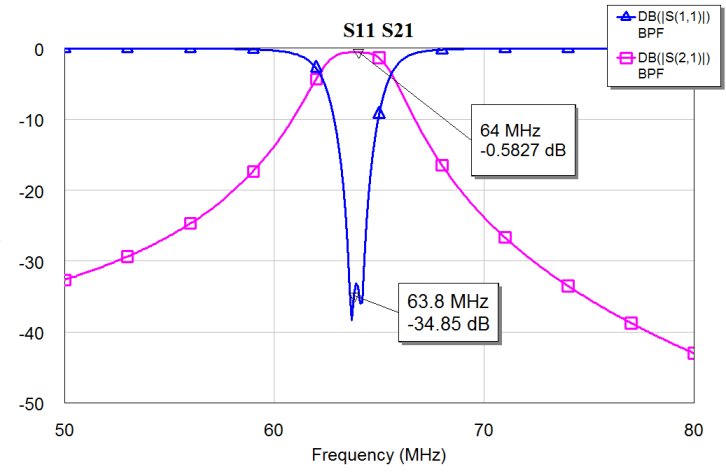
I don't know what you did wrong with your simulator, but results should be as in the picture attached.
I am using for many years this topology, without variable capacitors. T-type BPF require high-Q inductors, which anyway you need with any type of filter if you want to get less that 5% of filter bandwidth.
Thanks!
I managed to fabricate the filter and get a good response at 64 MHz with 3.1 MHz bandwidth. I have attached the response obtained on VNA.
However, the insertion loss is still high.....around -10 dB.
Thanks for your input.
I will get low loss capacitors as G4BCH suggested and high Q inductors as you said and re-fabricate for better results.
Thankyou everyone for your suggestions!


Can you please suggest the manufacturers of high Q inductors?
What should be the range of Q that I should look for?
Could you also suggest the makers of low loss capacitors?
Coilcraft makes good high Q inductors with very detailed and reliable characteristics, and a very good search tool. They suggest that this their 2222SQ series is optimal near 165nH, but it's Q is still just 159, which may not be enough for your specs.
It's easy to find cap values as requested in tight tolerance, no doubt.The problem is coming from inductor values and their Q factors.
I recommend you to use air core "hand made" inductor for those values ( 165nH ) in order to tune the right value.A proper emailed copper wire with few turns will give you a good inductor with high Q factor.They will also be tunable by stretching windings.
Also, pay attention the magnetic couplings between the inductors and of course PCB layout should carefully designed.
I have checked your circuit by applying some tolerances on L,C and Q values.Look at what is happening in 250 Monte Carlo simulations..


To get maximum Q of an inductor, one of the best choice is an air core inductor made from silver plated copper wire.
There are a lot of online calculators for air core inductors:
https://m0ukd.com/calculators/air-co...or-calculator/
To get an inductor near 165nH, need about 9 turns on 5mm diameter and about 10mm length. When the inductors are placed on the PCB, just tune a bit the distance between their turns to get the proper inductor value and for the required filter characteristics.
In this way at 64MHz, using 1mm thick silver plated copper wire you get an inductor with Q greater than 300 (and about 250 if use normal 1mm thick copper wire).
As was stated, the inductors should be placed at some distance with 90deg between their axes on the PCB, to minimize the magnetic coupling.
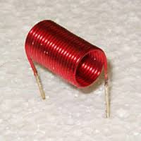
How is it possible to make an inductor with 5 mm diameter and 10 mm length?
Like This.
Hi,
What I meant is, isn't it physically impossible to have a wire of length 10 mm to be wound over 5 mm diameter with 9 turns.
Er... yes, but that is not what vfone was suggesting.
Usually the diameter refers to inside diameter.
So you get a 5mm drill, wind your coil, and maybe stretch it to 10mm (if required}.
That is the standard way of specifying a coil.

Oh I got it now...Thanks!
Yes...10mm is the inductor length, an not the wire length.
Usually wire length of inductors is specified ONLY for straight (or single round) wire inductors:
http://chemandy.com/calculators/roun...calculator.htm