Using an attenuator pasive probe with a spectrum analizer
I have find this document wich suggest the use of a passive probe in 1:10 to attenuate the signal to a spectrum analyser in order to be able to use signals above +20dBm.
The theory is easy, the 9M resistance is a voltage divider with the 50ohm internal resistance of the analiser so it will attenuate a lot. So let's see: I have a tektronix 1:10 probe like this one, with 9M and 17pF

The attenuation will be 9M/50 = 180000 = 105dB.
The problem I see is the capacitor, at DC the attenuation is OK, but when frequency grows the impedance of the capacitor decreases and the voltage divider stops working. For example at 150Khz Zc=62K then 62K/50= 62dB and at 433Mhz Zc=21ohm so the attenuator will be not working at all.
Am I wrong?
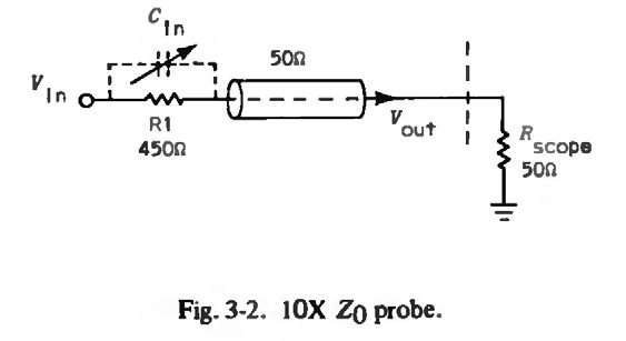
The article is suggesting a resistive 10:1 "Z0" probe, essentially a 450 ohm series resistor. High impedance passive probes are not suited for 50 ohm inputs.
See a picture from the classical Tektronix publication Oscilloscope Probe Circuits
a low frequency solution, like the X10 scope probe, will not work well with a microwave or even high frequency RF signal. I would NOT count on it being a 1/10th voltage divider either, since the spectrum an alyzer is a 50 ohm system, and a scope is typically a 1 Mohm system.
I would put a 20 dB 50 ohm attenuator at the spectrum analyzer input, and then hook a probe in front of the pad. Maybe a 100 pF capacitor in series with a 100 ohm resistor? The series capacitor keeps DC voltage off your spectrum analyzer front end, with on some units can destroy the spectrum analyzer. The series00 ohm resistor keeps from loading down your microwave circuit too much.
another way is to use a small capacitor, like a 1 pF chip ceramic at the end of a SMA sparkpug connector, the capacitor DC blocking AND reducing the RF signal by being a reactance.
Realize that without a 2nd pin to touch the ground plane of the circuit under test, the actual displayed rf power level will be all over the place, and not repeatable.
pasive attenuator probe 相关文章: