LVDS Modelling using ADS
Hi,
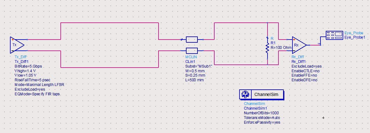
LVDS transmission line and it′s termination:
You didn′t try to find an anwer by yourself. So let me help you:
http://lmgtfy.com/?q=lvds+termination
Klaus
Hi, Thanks for your response. As I know Differential Transmitter in ADS can only output something like [-0.3 0.3] V. I want it to ouput [1.05 1.35] V to be input to the coupled line. However, if i set vhigh as 1.35V and vlow as 1.05V, then I get v+ as [0.525 0.675] V and V- as [-0.525 -0.675]. What I mean here is I wish to have a dc offset voltgae at about 1.2V and add it to both V+ and V-. Is it possible for channelSim?
Apparently Tx_Diff source doesn't allow to specify a common mode voltage. Solution: refer to the internal Tx_Diff circuit given in the ADS doc and make your own driver with common mode voltage. Or use a different way to make an appropriate LVDS driver.
Thanks. I use single ended transmitter to output [-0.3 0.3]V into ballun4port and add common mode voltage of 1.2V. That seems to solve to problem.