Amplify DRA818V Output Power
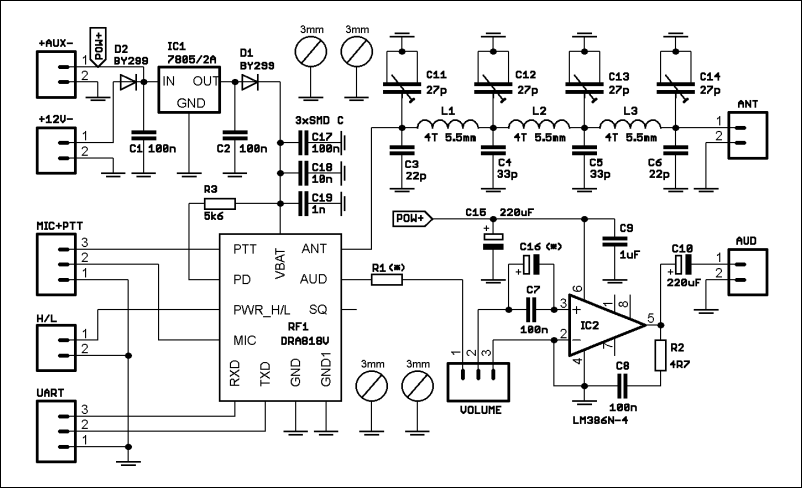
This schematic also includes LPF,But filter output is connected to antenna.
As already said I want to connect output to 1971 power amplifier before connect to antenna.
Should I use this LPF before 1971 amplifier circuit? Or shift it to output of 1971?Please help.
Thanks.
It wouldn't so any harm to leave the present LPF in place as it presumably already matches to the module output. If you remove it, you will almost certainly have to put something similar back in place to match to the new PA stage.
Unless the new PA is linear, I would advise adding a further LPF after it before the antenna as it will produce harmonics itself.
Brian.
Thank you sir for quick reply.I have another 2 questions:Does placing PA circuit like this:
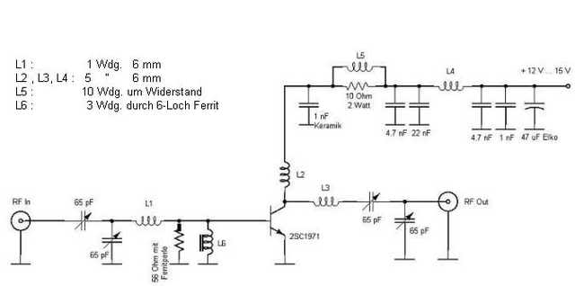
Impact in receiver mode and reduce sensitivity?
Without amplifying,I mean 1W module output ,Which one has more range:1W UHF or 1W VHF?
The PA circuit looks reasonable.
If you only add that circuit it will stop the receiver working completely, the signal has no path back from the antenna to the module. The simple fix is a dual pole relay that bypasses the PA when receiving and connects the PA when transmitting. A more complicated but reliable solution is to use PIN diode switches but they are much more expensive and may need additional power switching circuits.
1W on VHF has exactly the same range on UHF, it isn't the power that decides the range, it's the antennas and things along the path to the far end that make the difference. In general, VHF will work better but if there are no obstructions, the difference between them will be very small.
Brian.
Does anyone work with DRA818 and know maximum TTL voltage level?
Max VCC is 4V5 ,But I didn't find anything about TTL voltage in datasheet.
I think the maximum TTL voltage is 4v5 too,But I'm not sure and don't wanna risk.
It does quote "Absolute Maximum" Vin as VCC+0.3V so it clearly can't handle normal 5V TTL levels but I would think it safe to assume it can handle voltages up to VCC without any problems.
Assuming you are using a 4.5V supply:
To send a TTL signal to the module add a series resistor of 390 Ohms and a second resistor of 3.3K to ground from the DRA818V side. (across DRA818V input and ground)
Signals from the DRA818V should already meet TTL specifications so no interface is needed.
Brian.
Thank you sir.
You were right,I found this schematic,It uses 4v5 (7805 + 1N4007) for module VCC and MCU VCC and directly connect module TXD and RXD to MCU ,So TTL voltage is 4v5 too.
This question remember me about an old joke: What weighs more? 1 kg of lead or 1 kg of cotton?
But here, the situation is different. Triple the transmit frequency, let's say from 150 MHz (VHF) to 450 MHz(UHF), the path loss increase with 9.5dB.
So, 1W in VHF definitely has more range than 1W in UHF.