AD9834 DIY signal generator - please verify PCB/schematic
I am going to make a AD9834 signal generator - I will etch the PCB and solder the SMD components, but I like to ask first if the schematic and board is correct.
I have chosen to use the Roland Cordesses PCB project:
http://roland.cordesses.free.fr/dds5.htm
here is the PCB:
ad9834N_Cbd.pdf
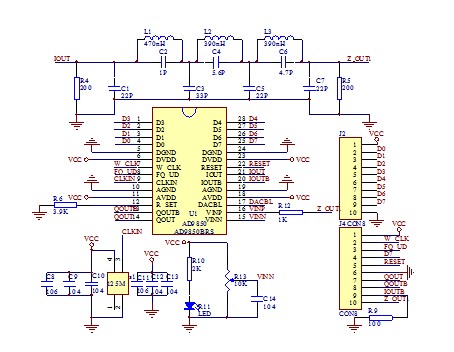
and the schematic:
gen9834.pdf
I am going to interface it with Arduino UNO.
and I have followingn questions:
1. Is this PCB and schematic correct?
2. How/where do I buy that U4 20MHz oscillator? There is no part name and searching for 20MHz yields me only common two-pin crystals like the ones used at OSC pins of AVRs and other MCUs
3. For the 20/40/80m receiver/transceiver VFO usage, I need a square waveform output, right?
4. How do I calculate that low pass filter there for the 20/40/80 bands, and do I have to use separate filter for each band?
I have seen such calculators, but how do I choose frequency limits, etc?
http://sim.okawa-denshi.jp/en/CRlowkeisan.htm
I'd like to get a wide band covered in my receiver.
5. Do you have any other suggestions/hints for me using that DDS project for my ham receiver?
Thanks in advance!
Buddy..
I admire your courage but you try to realize a complex project that exceeds your level.
1-Such PCBs should have double layer due to high GND noises.That disturbs everywhere including itself.
2-www.digikey.com ( or at some others like mouser,arrow but look at www.octopart.com to get more information and just search what you want)and pay attention the specifications !Some IC circuits need some special characteristics.
3-VFO should be a sine-wave to my knowledge.(not sure)
4-BandPass Filters for Amateur Bands have high out-of-band rejection and attenuation levels.RC filters cannot be used there.In order to get a reasonable result, crystal filters are best if they are available.
Those Filters can be connected in parallel with SPnT RF Switches or they can be inserted to the circuit mechanically ( jumper,a good high quality commutator etc.).Elliptic Filters can also be used and they are L-C filters at that frequency.More information, see. Filter Design Softwares.
I realize that it needs to be double layer and I will etch that. I just do the iron transfer method on one side and completly cover the second side and it works, it already worked in the past.
Is there anything else problematic I need to know?
I have tried to look in the shop I usually buy stuff but they charge over 11S for a single crystal of that type:

Suprisingly, the entire DDS module (altough a bit lower max frequency, over 10MHz if I remember correctly) costs around 5S there:

Well, the same I saw on the oscillscope when I was probing theVFOs
My friend gave me such schematic and said that Ican try just adjusting the component values for the filter showned here above the chips:
but right I nnow I have no idea how toadjust them.
By Filter Design Software, do you mean PC applications like http://www.nuhertz.com/ ?
Or maybe that: http://www.microchip.com/development...esign-software
You can get an AD9833 module (and also the Arduino board and components) from here:
https://www.aliexpress.com/item/CJMC...a-2097b571820b
and using the information from here:
https://moosteria.blogspot.com/2015/...generator.html
or information from here:
http://www.darc-husum.de/funktionsgenerator.html
you can build a signal generator with AD9833 for less than S10.