why Phase detector IC input pin reading is always the same?
I am software guy, don't have much idea about RF design.
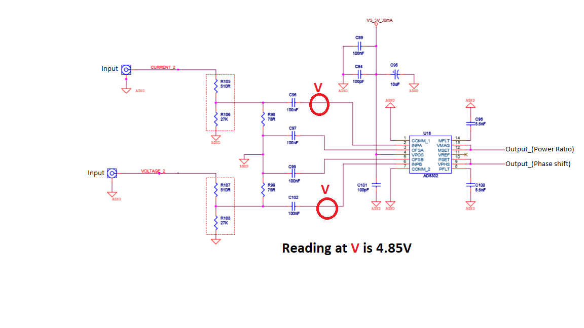
These days, I am trying to experiment on phase detector IC(AD8302). As attached figure, while trying to measure an input values at pin INPA and INPB, it always reads 4.85V. This reading is the same whether there is RF power or not. Actually, the output reading is correct as compare to phase shift on Oscilloscope. An input limitation(maximum) at those to pins is ?13dbV(0.22V) as it is described on the datasheet. Even that was why I added the voltage divider on the input side as shown in the figure. My doubt here is that, why the reading is always 4.85V and would it be safe? can input at pin INPA and INPB exceeds ?13dbV(0.22V) ?
I would like to thank all in advance.
Hi,
"Pin reading". What measurement device? What value us shown?
* "average" is just the DC offset, it may be the same value with or without RF
* "RMS" value can be with and without DC.
I'm not familiar with this application...but the IC is called "phase detector". It may operate similar to a logic "XOR" circuit.
Then the RF input signal may be constant, but with varying phase shift, the output signal will vary.
Best is you read the IC datasheet ... or go to the manufacturer's internet pages, and look for relating application notes to get more detailed informations about it's operation.
Klaus
Dear Klaus,
Thank you very much for your berief.
I just used oscilloscope and Multimeter to measure RMS value at pin INPA an d INPB. It shows 4.85 volts with and without RF Power. As I have understood from the datasheet, an input maximum is limited to 0.22V. But here it is 4.85V. On the other hand, it is the same(4.85V)all the time.
Thank you once again
It is the DC bias on the input pin, look at Circuit A on page 5 of the data sheet you will see that the voltage on the two pins is about 100mV less than the supply.
The maximum input referred to is the maximum signal the device can handle, the difference between INPA and OFSA.
Peter
It's internal DC bias voltage, not RF signal strength.
The RF signal level should be measured with an Spectrum Analyzer with a high impedance probe to avoid the performance degradation.
A high impedance probe can also be used with a high quality oscilloscope.
Hi,
A measurement is only as good as the knowledgement of how and what to measure.
If you want to measure the RF signal voltage, that is biased with DC voltage..
* you can't use "average" method
* you can't use "RMS including DC" method
--> you need to use "RMS excluding DC" method.
If your measurement tool can't exclude DC, then a simple RC high pass filter will do this.
Klaus
Klaus,
Thank you a lot.
I will try to measure accordingly
As already stated, in that point you should measure the power with a high impedance SA probe.
Any voltage measurements in that point are pretty useless.
The AD8302 datasheet mention very clear that the input power range is between -60dBm to 0dBm.
the digital gate is a non-standard one. Note that the RF inputs have to be AC coupled to those two input! I would not worry about the apparent DC voltage level at those two pins, just so long as it is still working as a phase detector.