Importing Patch antenna into ADS for rectenna
Can anyone help me regarding how we can import a patch antenna as a whole into ADS, or a rectifier circuit into CST. I read it is done using Momentum. Can anyone give me the steps to open the Momentum interface of ADS.
Thank you in advance. :)
How to design a rectifier with the impedance matching circuit for a patch antenna connected to the input?
-How to select the diode specifications?
-Is it better to use transmission lines or discrete components.
-How do we select the length and width and type of network of transmission line?
-If discrete components what kind of network and components?
Urgent Help needed.
Thanks in advance :)
What is the rectifier doing connected to a patch antenna?
What does the circuit do?
It is a rectenna circuit which converts RF power to DC. The patch antenna receives the ambient RF power.
Is your project similar to RFID? This topic has several discussions here. Try a forum search on rfid.
No, it is not related to RFID, it is a rectifier which converts RF to DC instead of AC to DC.
Any help would be appreciated :)
Hi, you can import your antenna as a gerber file and import in ADS ( you have to open a new layout).
I'm not sure what you want to simulate exactly but this is how you'd get your antenna on ADS.
Hello, thanks for the reply :)
I want to interface the antenna with the rectifier circuit and also design an impedance matching circuit for the same. I do not know how to design it since a schottky diode is used in the rectifier circuit.
Urgent help needed !
Using the gerber file, how do we import the substrate.
Define the substrate on ADS, simulate your antenna to get the S parameters then create the EM Model and symbol pf your antenna ( EM -> component -> create symbol and EM model)
Doing this will allow you to use your antenna on schematic and do your simulations.
Hope this helps!
Thank you very much for your help:) In ADS how do we design a one layer FR4 substrate and coaxial feed?
Any help regarding the impedance matching circuit ?
I would suggest viewing some tutorials on youtube, it's going to be quicker than me trying to describe to you where every button is.
For matching circuit use the smith chart tool on ADS(open a schematic then go to tools-> Smith Chart) it'll be quick and quite effective. otherwise you'll have to read on impedance matching.
Is your rectifier biased with some DC voltage or are you trying to build something like an RF harvester stuff?
Yes, I am trying to build an RF harvesting circuit. Can you help me regarding this circuit?
In that case I assume there is no bias for the rectifier circuit (which is typical). This type of circuit is very nonlinear meaning that its input impedance changes considerably with the available power at the input. For example, when you match your rectifier for -20dBm, the matching network probably perform poorly for -40dBm. Before you start designing the matching circuit you have to decide on the input power value, that should be your starting point and you gonna have to find the input impedance for that input power, you can design the matching circuit after that.
Do you know the basic theory? If you don't I suggest you to go over the basics. For that you can have a look the David Pozar's "Microwave Engineering" book. It is important to know the basics before you start. You don't have to read the entire book of course, just go over the relevant chapters for your project.
Questions:
1. how much power are you expecting to harvest from a patch antenna on FR4?
2. you mention interfacing the rectifier with the patch and also a coaxial feed, which do you intend to use?
Brian.
Thanks for the reply :)
1. I want to check how much power can be harvested by varying the power at the input.
2. do we have to feed the patch antenna while using it for rf harvesting, because mine is coaxially fed? I do not know exactly what is the procedure.
Thank you for the reply :)
The input impedance for the impedance matching network will be 50 ohms, right?
And then the load impedance would be that of the rectifier.
How can we find the impedance of the rectifier since it has a schottky diode in it?
Matching network should be designed in such way that it converts rectifier's input impedance to the antenna's input impedance so that they are matched.
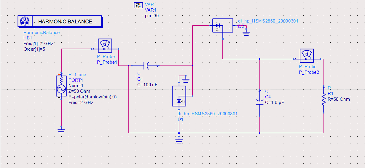
Try to run harmonic balance analysis and connect current probe at the input. You should convert the input power to voltage and divide it by input current, that's how you find the input impdance. The impedance changes with two parameters, frequency and available input power. As you vary the frequency or power at the input you should get different results.
What is the method to find the rectifier's input impedance?
Can you please check the circuit and tell me what improvements can be made ? The software is ADS

