Implementation of CPW power divider in ADS at 33 GHz
I want to implement a CPW power divider in ADS which can work at 33 GHz.
According to the 1st and 2nd attached images, using LineCalc tool in ADS, I have designed the CPWs for power divider for 50 and 70.7 Ohm characteristic impedance.
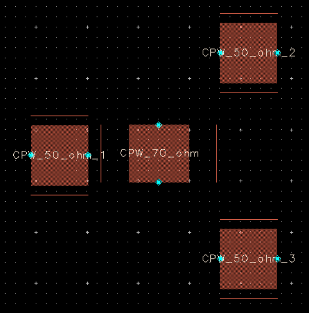
According to the 3nd image, the length and width of CPWs are close to each other so that I can't attach them together in layout window.
My question is that how can I implement the layout of such CPW power divider at 33 GHz?
1st image:
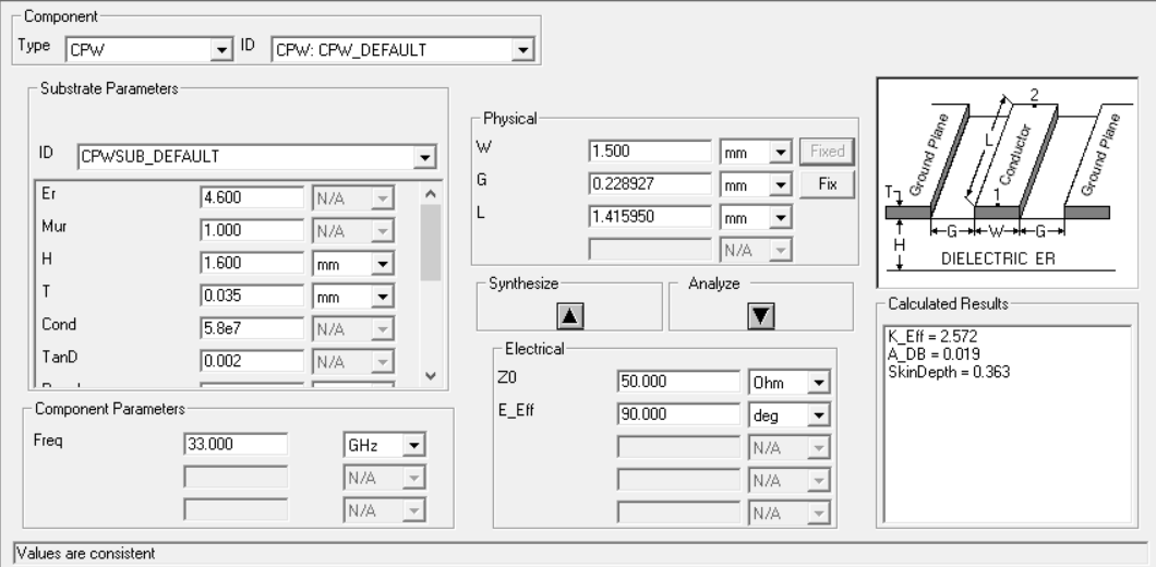
2nd image:

3rd image:
You defined 1.6mm FR4 in linecalc, which obviously makes no sense because it's too lossy and substrate height is much too thick for 33GHz use. Thick substrate results in wide lines, and if it's so very thick relative to wavelength it radiates heavily. Use a thin substrate from low-loss material suitable for mm-wave work, e.g. RT/duroid, then you get useful dimensions for line width.
In the ADS layout elements, the thin lines indicate the edge of the side grounds.
Dear volker,
Thanks for your great guide, but i have no sense of standard line parameters, such as FR4 and thickness.
Would you please help me how to select line parameters, consider that i dont have any choosen technology.
Thanks a lot.
If you don't have any choice of substrate but FR4, forget the project..
FR4 will definitely not work at 33GHz.
So, I understand that i must choose a technology which thickness and height are obtained, in addition, this technology should work at 33 GHz.
Would you please how can I choose a technology?
And where can I find various technologies?
Maybe these papers from John Coonrod (Rogers) give a starting point:
https://www.rogerscorp.com/documents...plications.pdf
http://www.microwavejournal.com/blog...llimeter-waves
power CPW Implementation 相关文章: