[Square Patch Antenna w/ Dual Feed] Asymmetric Radiation Pattern
时间:04-04
整理:3721RD
点击:
Hello everyone,
I am currently simulating a square patch with dual probe feed, as you can see on the following image:
The distance from the centre that I chosen for both probe feeds is the same. Afterwards, I used two wave ports for each one of the probe feeds.
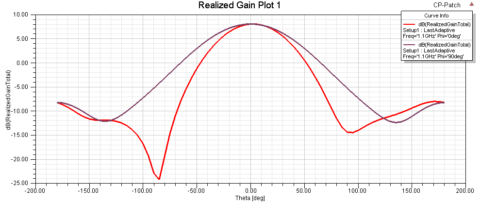
After that, I plotted the Realized Total Gain for both phi = 0 and phi = 90. As expected, when theta is 0 the gain for both phi = 0 and 90 is the same. However, as soon as the theta deviates from the centre value one of the polarizations, namely phi = 0, shows a more severe gain degradation.
Hence, this is currently bothering me since I was expecting the profiles to be very similar, as occurs with the reflection coefficients of each port.
Likewise, the total peak realized gain of the antenna on this plot is nearly 8dB, while the HFSS 'Compute Antenna Parameters' option in the radiation sphere reports a peak gain of 6.4dB, which appears to me more practical.
Is there anything that I am doing wrong? Or this situation normal? If so, please someone provide me a explanation on this.
Thank you for your time.
Kind Regards.
I am currently simulating a square patch with dual probe feed, as you can see on the following image:
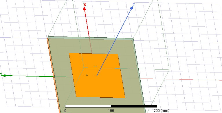
The distance from the centre that I chosen for both probe feeds is the same. Afterwards, I used two wave ports for each one of the probe feeds.
After that, I plotted the Realized Total Gain for both phi = 0 and phi = 90. As expected, when theta is 0 the gain for both phi = 0 and 90 is the same. However, as soon as the theta deviates from the centre value one of the polarizations, namely phi = 0, shows a more severe gain degradation.
Hence, this is currently bothering me since I was expecting the profiles to be very similar, as occurs with the reflection coefficients of each port.
Likewise, the total peak realized gain of the antenna on this plot is nearly 8dB, while the HFSS 'Compute Antenna Parameters' option in the radiation sphere reports a peak gain of 6.4dB, which appears to me more practical.
Is there anything that I am doing wrong? Or this situation normal? If so, please someone provide me a explanation on this.
Thank you for your time.
Kind Regards.