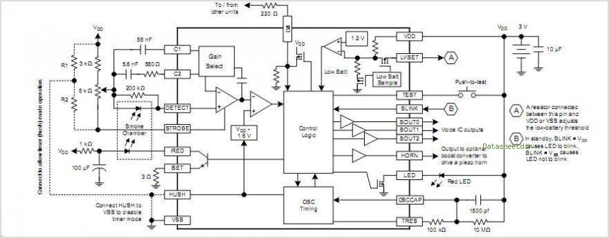
Smoke detector circuit with A5303
This is datasheet.
I would expect unsuitable design of the detector chamber as most likely reason. Can you show a drawing?
Hi,
Give an error description.
"It doesn't work like explained" is not very informative.
Klaus
But the chamber is OK! I have problem with oscillation frequency that as stated in the datasheet is determined by a capacitor and a resistor that are parallel to each other and are connected to the OSC CAP and Vcc as shown in the below (1500pF and 10MOhm) and is equal to 0.7*C*R. Sometime when I place a cap and res connected to this pin the circuit works and oscillation frequency is correct, but after a while the frequency becomes lower than before or the circuit doesn't work at all! and this time when I measure the 10 MOhm resistor in the circuit by multi-meter It doesn't show true value and is very lower! What can be the problem!?!

Are you sure that the 10 MOhm resistor can be measured in circuit?
How do you check oscillator operation? Probably difficult with standard 10 MOhm oscilloscope probe.
The LED pin in the above circuit blinks every 500ms if the oscillation frequency is correct.But its blinking frequency is very higher while the values are correct! I think the problem may be with my regulator,because when I disconnected the regulator and supplied the circuit with a power supply it worked well. I want to have two power supply for my circuit,one from a 3volt battery and one from 12 Volt adapter.after 12V adapter is a switching regulator and after 3V battery is a boost converter to provide 3.3Volt. I used the below circuit for this. If the 12Volt turns off the 3V battery should supply the circuit.Is this circuit correct?
Hi,
simple test:
measure the supply voltage
* when battery is active
* when battery is not active.
Tell us the values.
Klaus
The supply circuit works but when I connect it to smoke detector, the smoke detector doesn't work well while the supply voltage is ok!
Hi,
The circuit surely doesn't work, at least not the way you think it works.
Too bad, that you didn't give the requested values.
Issues:
* the resistor values are not suitable. They consume at least 300 times the current of the smoke detector...and all this from the battery.
* the TL081 is not suitable to operate from3V single supply
* the TL081 output voltage range is not suitable to drive the MOSFET correctely
* the TL081 input common mode range is not suitable
* the MOSFET V_gs is not suitable.
What really happens:
* either the diode 1N4148 is conductive...with a huge voltage drop of about 0.5...0.7V
* or the MOSFET internal body diode (not shown) is conductive, with about the same voltage drop
* and there might be a case where the MOSFET is partely conductive..with a resistance mabe in the range of some kiloohms.
Functionally the same could be done if you leave the 1N4148, replace the Mosfet with another 1N4148 and dissmiss all other parts.
Then you are low power and don't need 500 times bigger batteries.
Or simply use a single BAT54C and reduce the voltage drop.
Klaus
Thanks for your answer. Is it better to place two diodes (or BAT54C) for switching between two power supplies or to use above circuit?! What is the advantage or disadvantage of your suggested circuit?
Hi,
I don't see any disadvantage of a single BAT54C against your circuit.
Even better - because less voltage drop - use an "ideal diode" circuit..
Klaus
What about the power consumption?! Doesn't this circuit consume more power from battery because of forward bias current of diode?!
Hi,
A diode consumes no current.
The current through the diode is determined by the load.
There is a voltage drop at the diode. Read the datasheet how much voltage.
Klaus
My circuit works well when testing by test push button or when I open the chamber and detector receives light, but when testing with real smoke it doesn't works and doesn't detect smoke! What can be the problem!?
Can anybody help me please?! What kind of IR LED and photo-diode I should use to work correctly?
It sounds as though the photodiode needs to be adjusted until you find what's known as a 'good operating point.' I believe you need to adjust bias through the photodiode, so that its idle state reaches a point where the slightest change of light level causes a change in its output. You may find you need to apply greater gain as you amplify diode response.
Thanks for your reply. But how can I change the gain?! Is the value of resistor that is parallel to photodiode important?!
Can anyone explain how does this circuit work?!
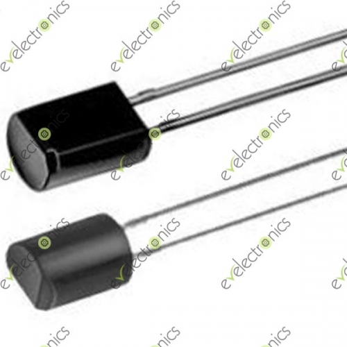
When I use 5mm IR LED and detector (like figure below) it works correctly when chamber is open,

but when I replace IR LED and detector with 3mm ones (like figure below) it doesn't work even when there is not any chamber and emitter-detector are in front of each other! What is the problem!?

Smoke reduces intensity of the light source, causing a certain amount of voltage (and/or current) response in the detector. You need to discover how the photodetector behaves in the expected light levels. You need to amplify the change in response. Design your circuit to send either an On or Off status to the alarm.
You probably didn't even understand the operation principle of an optical smoke detector. It's light dispersion, not absorption. Respectively the transmitter and detector should never be placed in front of each other.
