Which solver and mesh settings to use in CST?
时间:04-04
整理:3721RD
点击:
Hello everyone,
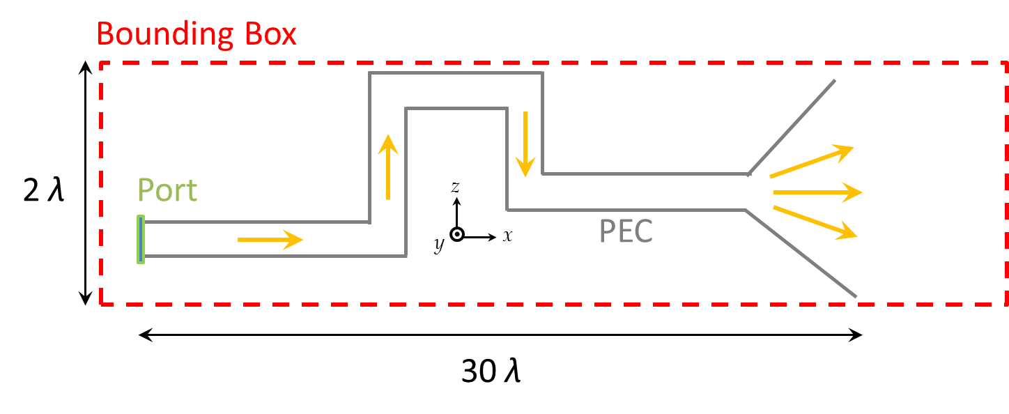
I am currently working on a model in CST, which is shown as a rather simplified cross section view below (not to scale obviously).
The structure is basically a parallel plate waveguide with zero-thickness PEC walls, with relatively large width (20λ in y-direction). The model is about 30λ long in x-direction and ends with a horn-like radiating aperture. Moreover, there is a spacing of several λ behind the radiating part, that is in positive x-direction. The bounding box is around 2λ high in z-direction.
At the end of the day it would like to simulate the structure within a bandwidth of around 10%, but for now only one frequency point would be sufficient.
So far I have only worked with CST's time domain solver. When using this one, a mesh within the entire bounding box is created. This means that all parts surrounding the waveguide are also meshed, and the resulting mesh cell number is quite high (70 Mio for default settings). Unfortunately I was not very successful in reducing the mesh cell number in this regions through local meshing. For me the relevant volumes would be only
- inside the structure (between the parallel plates)
- outside the waveguide only in and behind the radiating aperture
What I've learned so far is that when using HFSS instead, its frequency domain solver only meshes the "inverse" of the shown model (that is the interior of the waveguide and some parts for the radiation boundary), while the surrounding space is PEC which is not meshed. The computation time is thus considerably lower
Therefore I was wondering if any of the other solvers in CST is preferably used for this type of problem?
Tom