[ADS] Spiral inductor parameterization in ADS
i believe its called parameterization.
the correlation between schematic and layout is given below. blue is schematic and red is the layout.
Why do you have negative inductance? Please show a wideband plot down to DC.
Parameterized EM: I had written an appnote on that topic, showing different methods to create the layout
http://muehlhaus.com/support/ads-app...eters-momentum
my filter circuit required negative inductance in order to meet the goal of insertion loss and rejection.
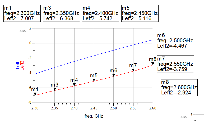
attached the inductance from DC to 2.6GHz.

Leff is circuit simulation whereas Leff2 is layout simulation.

Please refer to the Q and Reff of the layout simulation of the negative inductor.
this is when i simulated with CPW components in ADS
Dr Volker,
i followed the steps you have given in the document and i got below error.
error message.txt
this is solved.
Dr Volker,
i followed the steps you have given in the document. when i tried to optimize the coil to meet the circuit simulation, nothing happened. meaning, the coil parameters did not change.
i was intended to change N (number of turns), W (width) and S (Gap). i did Customize Pcell and re-simulated the layout but the optimizer still not able to change the N, W and S. Please help.
now im not getting any error message but the layout is not changing i believe..
the optimizer is saying no improvement is possible..
Have a look again at my appnote, near middle of the page, title "Bug or feature?"
http://muehlhaus.com/support/ads-app...eters-momentum
I guess this is your problem: You need to change a setting from ?Use this layout? to ?Parameterized?.
Have you tried replacing the negative inductance by a capacitor?
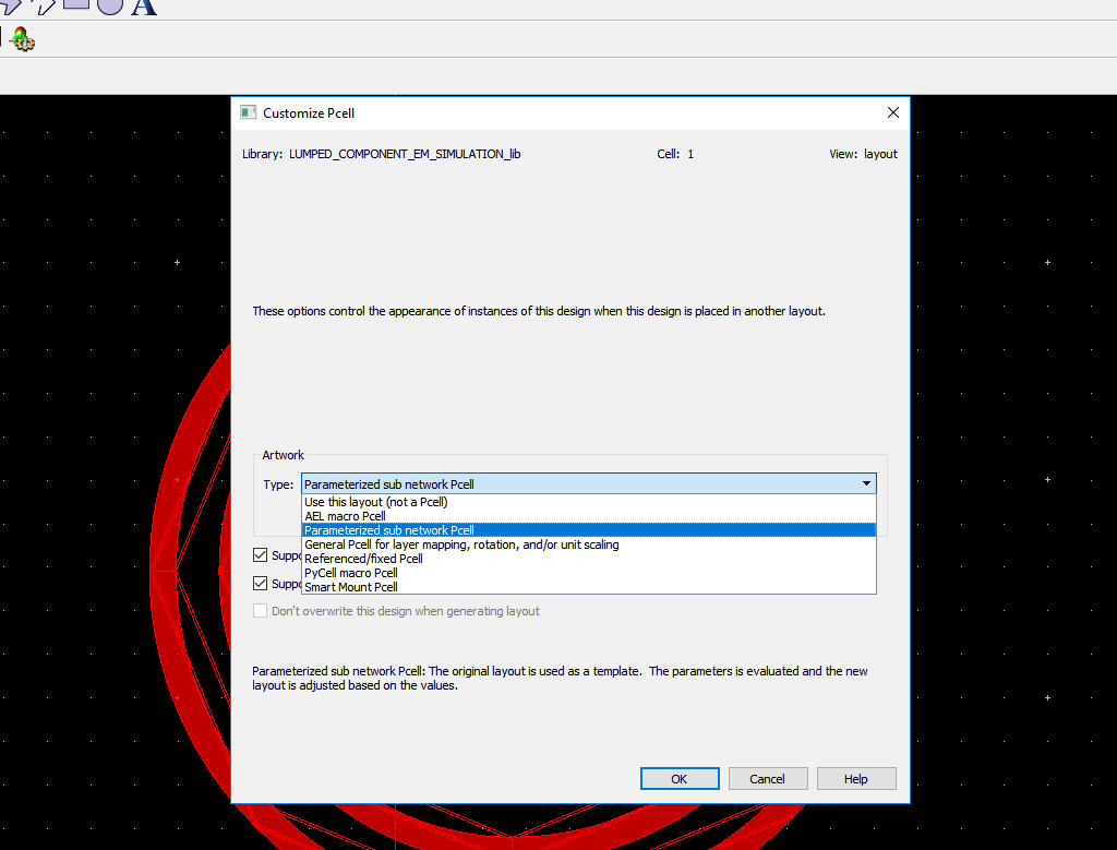
please refer to the attached pic. i did changed to parameterized but its not still not changing. i repeated the exercise many times but still the same..
I did but it did not work. I think it because my filter is seeing negative to positive reactance as the optimum point.
That looks fine.
Have you defined all the cell parameters, and pass them to the spiral ?
You can test your parameterized cell by placing an instance into a new layout, and see if it changes when you modify parameters.
I can have a look at your element, please copy to a separate library/workspace and upload here.
no, I didn't do that. i only did every step in your link that you sent me.
LUMPED_COMPONENT_EM_SIMULATION_wrk - Copy.rar
attached the project. Please let me know how to define cell parameters and pass them to the spiral. I think thats what im missing.
Your workflow/method is not clean.
There must be no schematic in the cell, that is what causes you trouble: you have defined variables in the schematic VAR block. That is wrong. The values that you pass to the cell must be defined as cell parameters (design parameters). Only then, you can control the values when placing an instance with parameters.

Delete the schematic, there must be no schematic in this cell. Define missing cell parameters and make the inductor use them.

Use a separate cell for your schematic testbench.
done. please see the pic below. my new layout name is "1".

done. please see the picture below.

also done. please refer to the pic below.

but unfortunately, my optimizer still not able to change the parameters!
if you able to optimize the spiral layout in the file that i sent you, please let me know. im still not able to do it
dr volker,
i didnt define Ri in the cell parameter above. i have redone the simulation after defining the Ri. However, my optimizer says "no improvement possible" in the 1st Iteration/Trial as usual! so no difference is detected by adding Ri.
hpeesofsim (*) 490.shp Nov 12 2018, MINT version 4
(64-bit windows built: Tue Nov 13, 2018 02:20:54 +0000)
OPTIM Optim1[1] <LUMPED_COMPONENT_EM_SIMULATION_lib:new-sche:schematic> optIter=(0->25000)
SP Optim1[1].SP1[0] <LUMPED_COMPONENT_EM_SIMULATION_lib:new-sche:schematic> optIter=0 freq=(2.3 GHz->2.6 GHz)
Iteration/Trial #0:
CurrentEF: 311.629187474297
Optimization variables:
X2.N_turns = 4.5487
X2.Ri_inner_radius = 616.705974612e-06
X2.S2_gap = 251.149866e-06
X2.W2x_width = 155.585668e-06
i dont understand why "mil" is defined as e-06 here! Is this the rootcause?
But this is wrong - you have fixed values for the MRIND, instead of using the cell parameters.
To test, create a new layout in a new cell. Place an instance of you parameterized cell and change parameters. If it scales - great. If it does not scale, something is wrong.
I have created a quick example workspace for you
scale_mrind_wrk.zip


