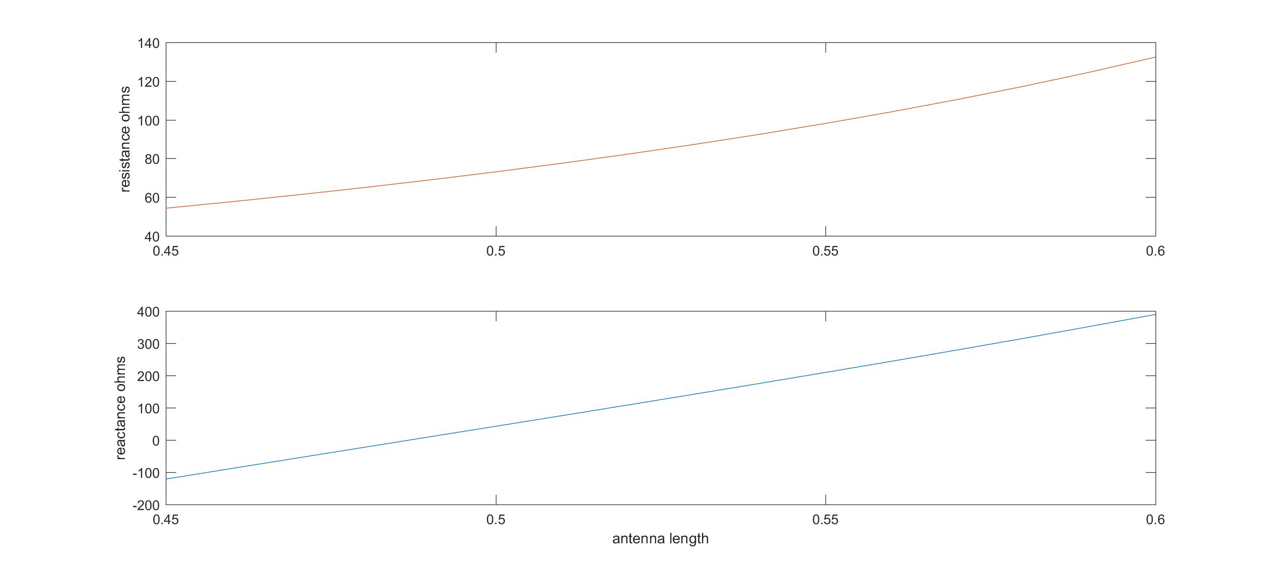
impedance matching trade off

To gain the best match, the antenna impedance should be 20+200j.
From the figure, I can't match both the resistance and the reactance. What's the best length I can choose to match better?
Should I choose to match the the imaginary part? So that I get the impedance 100+200j for the antenna.
Thanks.
Why do not use a matching network in between ?
I can't use the maching network in this application. Thanks.
Resistance mismatch is just as bad as reactance mismatch as it is total impedance error that cause reflection losses.
It is no advantage to focus on just one of these parameters.
Guess your curves are based on a hypothetical dipole antenna.
Dipole antenna impedance can be adjusted in many ways that not follows these curves.
As it is a dipole can feeding transformation be done as a part of antenna structure for adjusting measured resistance. It is a very common method. Gamma match/hairpin matching is a such example.
Also reactance part can be adjusted by antenna design by varying structure thickness and width along antenna length as well as bending parts of antenna elements in different directions and heights above ground.
RFID chip impedance is not same value at chip as at antenna feeding point due to phase delay in transmission line at PCB.
If not measured is 20-200j then probably the impedance value at chip, given from a data sheet?
If you tries to match an antenna based on hypothetical curves and a radio data sheet will it most likely fail.
Better then to keep antenna as a halfwave dipole and wait with correcting antenna and radio impedance until measurements are possible.
Indeed it is a quite limiting constraint, once at least in theory, part of the unmatched impedance could be eliminated by using antenna stub; anyway you did not specify whether it has to deal with a narrow or broad bandwidth.
I would suggest:
1. Measure the actual impedance at the point where antenna is connected to. It seems that the impedance 20-200j is from the datasheet? I don't know what frequency your chip operates at. For high frequency RFID, you may use a transmission line to change both the reactance and resistance (most like a transformer);
2. Match the resistance first. Then put a small inductor or capacitor to conjugate match the reactance. Since RFID is narrow-band signal, you will get very good matching with just one component.
impedance matching trade 相关文章:
- Output Impedance Of a Triple cascode
- How to make image impedance equal
- Input and output impedance matching in Distributed amplifier
- Characteristic impedance of combination of CPWG and stripline on inner layers
- Problem of impedance matching of Gilbert cell mixer
- Input impedance of transmission lines connected in cascade
