s parameters from simulation not as same as s parameters from datasheet BY ADS
i tried to extract s parameters for bjt bfr96 amplifier for specific Q point(VCE=10V, IC=50mA) from s parameters simulation in ADS 2017 but it not as same as bfr96 datasheet.
i know the S Parameters from vendor datasheet is reliable, but what about the S parameter simulation?
thank you in advance!
They should be close within 5-10 %
You use Nonlinear model of BJT, Gummel-Poon Model.
Use S-parameter model not Nonlinear model.
I believe S-parameter model not Nonlinear model since former is a raw data without approximation due to fitting.
See http://www.designers-guide.org/Forum...73409182/11#11
Does your nonlinear model include package parasitics, or just the bare die?
yes volker whan i put the SPICE MODEL inside BJT_Model(BJTM1) i got a strange S Parameter at the same Q point, at the same time when i simulate defulte BFR96 model i almost got close result.
i attached the BFR96 spice model from NXP.com .
when and how can i use spice model for simulation?
thank you in advance!
I do not recommend you to use BFR96 ( if you have really an intention to use it ) because it's obsolete and not manufactured anymore. I suggest you to go Infineon for discrete BJT Transistors and download their Design Kit.They are more consistent..
thank yo Mr BigBoss but it isn't my problem. my problem is what is the suitable model to put inside transistor to get real result (like S parameter for specific Q point) as same as datasheet?
i appreciate your help!
thank you so much!
If you have used the .MODEL from your file, it does not include the parasitic model (package).
.MODEL Declaration does not include Extrinsic components.If you would to fit measured s-parameters and model based s-parameters, you have to define additionally these extrinsic elements.
If you have a SPICE file with package parasitics, you can import this file in ADS.ADS will recognize SPICE Model and connect these extrinsic elements to the model.Then you should create/copy a symbol to able to simulate it.

thank you so much Mr BigBoss.
i imported spice model netlist for BFG97 transistor but i don't know how i can link and connect with (simulation amplifier circuit) from design guide and netlist spice model for bfg97. is there example or video please!
i'm sorry but i'm beginner in ads simulation...
thank you so much


Good.. Now create a symbol from this schematic.(Window-->Create Symbol then copy existing symbol) then call it back from Library into main simulation schematic.
thank you sooo much.i succeeded finally, every thing is ok but please i want your opinion about the comparison of (simulation and S2P) S parameters result please!
@ VCE=10V,IC=30mA, f=200MHz.


Looks consistent..
Thank you so much Mr BigBoss
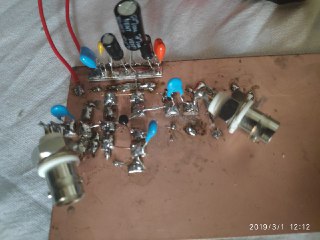
Mr BigBoss i just made this circuit practically and simulation.
in simulation with real model for bfg97 (PACKAGE : SOT223A DIE MODEL : BFR96) i got vout=145mV @ vin=10mV but in real circuit i got only vout=75mV @ vin=10mV.
what do you think for that please!
thank you so much


-Your simulation set-up is not correct
-Your layout is not properly designed..( frankly looks terrible..)
I recommend you to read some textbooks and ADS Tutorial to learn RF techniques then work hard to get practical skills..
Hi,
I′m not very experienced with HF...
In my eyes - maybe it doesn′t look nice - but it should be way more suitable for HF than a breadboard circuit.
The picture isn′t very detailed, so I can′t follow the signal... but it′s only 40MHz as far as I can see in the schematic.
Aside the esthetics - is it really that bad as testing circuit?
Klaus
The frequency may either be 40MHz or 40GHz, doesn't matter but the main principles must be maintained in any case.
It does not have to be look professional but minimum connection rules must be applied to get a healthy result.
Simulation set-up is not correct because he used a Vsin in series a 50 Ohm port element , it's not the same thing with Psin with internal 50Ohm source impedance.
He aims to fit s-parameters with nonlinear model results so the same condition for s-parameters should be provided.
I suggest him to learn the right things.
yes in picture it looks 40 MHz but i'm tried at 100MHz and 200MHz it's also not consistent.
i just wanted to make class a amplifier with real model, i know should maybe put RFC inductor with collector but i didn't tried with it.
really i'm confused if i must put terms 50 ohm in front of source or not, because the tester i used it has 50 ohm inside input wave terminal.
my main question is can i use nonlinear (spice) model for making amplifier circuit simulation like that class a circuit ?
is there example or reference explain vhf practical and simulation circuits?
thank you my friends soo much!
is there answers please!
