Re: need 7pF to 10pF at 2.5GHz
i have another question. can we do design LTCC implementation in ADS?
Sure. We used Sonnet EM and Empire 3D EM, but basically any layout tool plus EM solver is possible.
mistake.. pls ignore
dr volker,
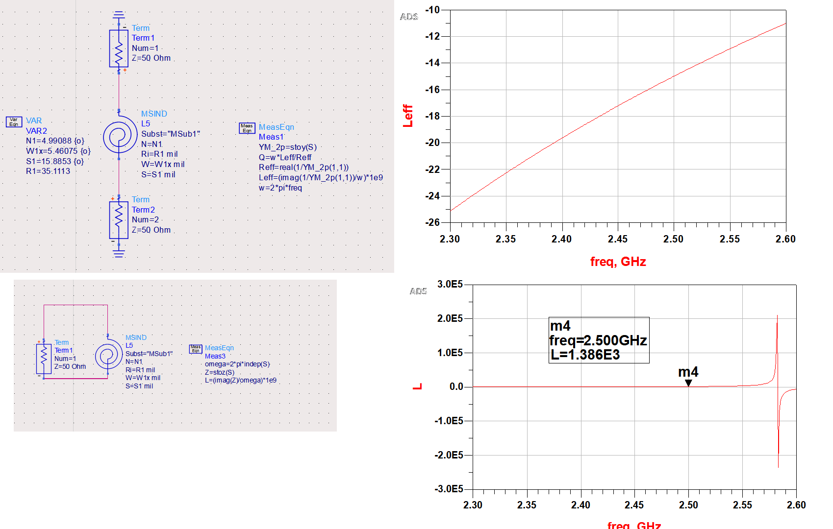
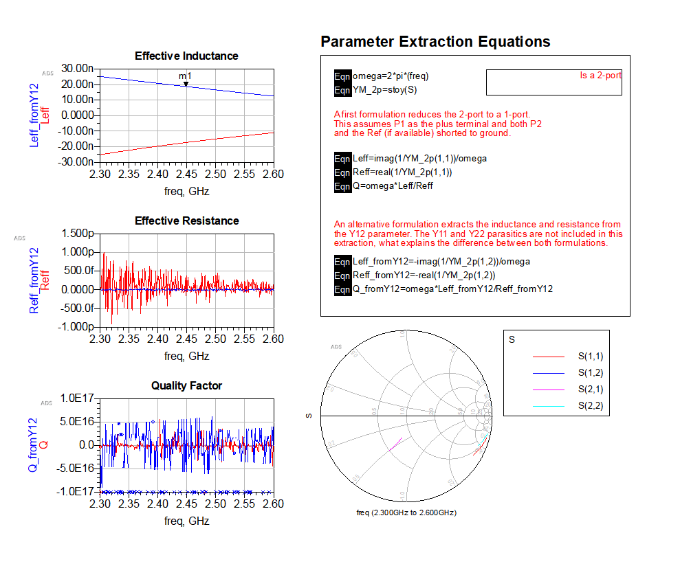
i have one last question. im getting different inductance when i simulate using a different set of formulas. Please let me know which one is correct and why?

results and formulas are attached side by side. the 1st formula is from ADS template.

ADS template have two method. extracting ind from Y11 and also Y12! both giving totally different results. Y11 shows -ve inductance whearas Y12 shows positive! which one to believe!
There is no "correct" or "wrong" equations, they are valid under certain conditions, as mentioned in the ADS template.
Assume you have an inductor represented by a pi model, with series RL and shunt C to ground. You can then extract the pure L from the series path (excluding shunt effects) or the effective series inductance (including the effect from shunt components), or the effective input inductance into one terminal when the other terminal is shorted. You then get 3 different curves. All are valid, just different what you consider "the inductance". So you need to decide what value is relevant for your design use.
this inductor connected in series and not shunt to ground. Pure inductance and resistance extraction (Y12) shows +ve ind which is correct. shunt to ground inductance (Y11) shows negative inductance which is not my case.
this is a differential measurement of the inductor using reactance (imag(Z)). its only valid for differential configuration which is also not applicable for me. the best is two port measurement.
But your inductor has parasitics: capacitance to ground.
That is possibly correct due to parasitics. Can you upload the inductor *.s2p, so that we extract the equivalent circuit model?
I agree that you should use the full S2P data in circuit simulation. I just tried to explain why there is more than one correct answer regarding "the inductance value".
I think the problem is not considering the prerequisites of ADS distributed components. MSIND is a microstrip inductor, it's referring to a MSUB microstrip substrate definition creating a respective shunt capacitance. Reading the ccdist manual thoroughly should clarify everything.
Place a lumped inductor, e.g. AIRIND1 model and both setups should give equal inductance.
could you please clarify what is ccdist manual?
Can you upload the inductor *.s2p so that we have a useful data basis for discussion?
Dr.

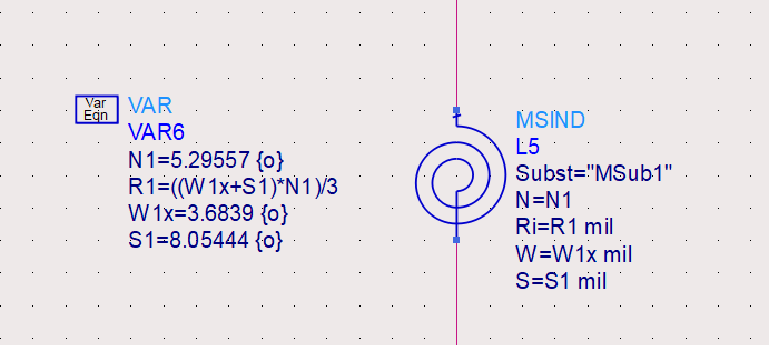
actually, I don't know how to generate an s-parameter file from the ADS. due to that, i sending you my coil parameters. you can simulate it and get the S-parameters. sorry for the inconvenience caused.
In the ADS data display menu: Tools > Data File Tool
This can create SnP from simulation dataset
thank you so much Dr. Volker. i have created s2p file. please refer below.
coil.rar
Data starts at 2.3GHz, which is not enough to extract a model. Please provide wideband data that goes down to DC.
attached the s2p as requested. thanks.
coil_2.rar
Indeed, your inductor has enough shunt capacitance to ground to become capacitive in some port configurations. Here is a simple pi model, extracted from your S2P:
.subckt SON3_38 1 2 REF
C_C1 1 REF 0.109335pf
C_C2 2 REF 0.105086pf
L_L1 1 3 63.69988nh
R_RL1 3 2 1.0e-5
.ends SON3_38
If we evaluate Y11 (port 1 input impedance with port 2 shorted to ground) it looks capacitive at high frequency because we then have 63.7nH || 109fF.
If we use the differential port configuration, we have a higher SRF because then 63.7nH || (109fF in series with 109fF)
ccdist = "Circuit Components Distributed Components" ADS manual
Dr Volker, how did u extract the exact C associated with the coil?
I went the easy way and used the Sonnet PI model extraction.
You should be able to get a similar answer in ADS by extracting the shunt path elements. For your convenience, I have posted some code from my Inductor Toolkit model extraction.
Y = stoy(S)
omega = indep(S) * 2 * pi
Cshunt_port1= 1 /(-omega*imag(1/(Y(2,1)+Y(1,1))))
Cshunt_port2= 1 /(-omega*imag(1/(Y(2,1)+Y(2,2))))
Reading these makes me sad about my job. How can I find people/material to help me learn about these stuff?
I am currently suffering from a similar phenomeon on extracting the parasitic values of (lumped elements+TLIN) in matching circuit. I need to model my elements and TLIN's in a better way; but have no clue on where to start.
what is the best impedance we should design the interconnect so that it won't form an inductor? 50ohm? or 75ohm?
