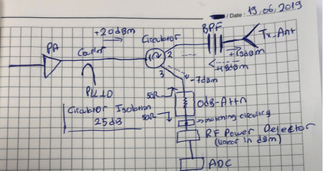
Using a 0db Attn as termination
I am trying to incorporate a RF power detector in my circuit at C-band to understand if a discontinious cable or a rusty connector exists between my antenna and PA.
I have a circulator after my PA to protect the circuit for reflections. Circulator's unused port is terminated with 50ohm to dissipate the power reflected from mismatches(normally). I want to show a 50 ohm termination to that port while simultaneously sampling the power in-line with a detector.
---Can I use a 0 db attenuator to show circulator's 3rd port 50 ohm termination while sampling the reflected power with a RF power detector. I tried drawing a schematic where normal lines are forward power and dashed lines are reflected power in case of a discontinuity, is this logical?

Kind Regards,
ktr
What do you mean by 0dB attenuator? In your drawing, is that "0dB" device a ferrite isolator or why does it provide isolation?
Hello Dr. Volker,
Thanks for replying. That's the part I'm struggling to figure out, if reasonable. If not properly terminated circulator does not work; hence I thought maybe a 0-db attenuator will provide the 50-ohm match to circulator. In MaximIntegrated site there is a similar topology given; picture below.
This is the datasheet of the 0-db attenuator I mentioned.
https://www.mouser.com.tr/datasheet/...or-1154282.pdf
From your datasheet, that is a series of SMD attentuators. Different values including 0 dB can be used for post-layout level adjustment.
The attenuator will improve matching by 2*A dB, where A is the attenuator value in dB. The 0dB will behave like any other thru line, it doesn't improve return loss.
