Power efficient oscillator topologies?
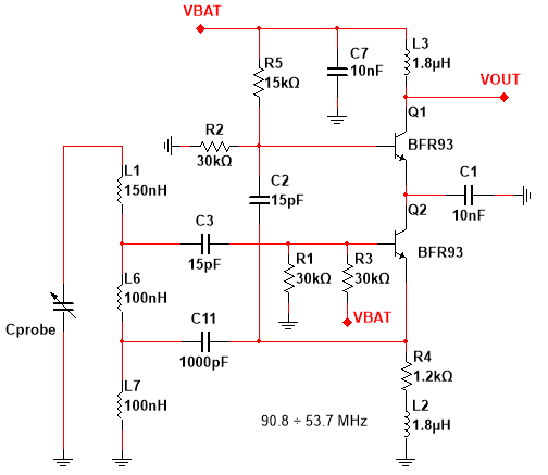
I've built a cross-coupled class D oscillator and I got 3 times Vcc at the output while consuming only 1.2 mA! But it's a differential oscillator so I can't use it because the probe is not differential and it can't handle the whole possible capacitance range. I also saw a class-C Hartley oscillator that has higher efficiency by the looks of it but I don't quite understand how it works and how to change the circuit for my application.
So is there any oscillator topologies that are more power efficient than the one I'm using and still sensitive enough to capacitance changes?

Cascode topology is basically reduce output swing, and above circuit only use cascode transistor to save DC current of a 2nd stage, it works as common-emitter amplifier from AC standpoint by C1 and C2. You should use a common source colpitts oscillator rather I think (basically disconnect C1 and C2, and Q1, connect Q2 and L3), cascode Q1 CE amplifier shouldn't be necessary.
Hrm. And what about Colpitts sensitivity compared to Lampkin topology?
UPD: I did as you say, removed Q2 and other stuff and I got only 450 mV output.
I'm also getting increased swing when I remove L1 but sensitivity suffers significantly. I can reduce coupling capacitors but it will reduce the swing so there's not much point in doing that.
Amplitude depends on capacitance (and inductance) ratios too, you have play with them. Or on bias, you have set almost half of the supply voltage on Q2 emitter, wasted the supply voltage a bit. Hard to say exact answer, there are more elements compared to usual Colpitts oscillator, I don't see why those are useful. With a simple colpitts it is possible to reach Vcc amplitude oscillation with suitable device values and transistor.
And please share a bit more info, like node waveforms, Cprobe value, max consumption, max distortion, etc. It would be easier to suggest the best solution.
What is the frequency and what is your target ?
I have trimpots instead of actual resistors, I adjusted them for maximum swing.
Lampkin topology is basically like Hartley but with an additional inductor for better LC tank decoupling.
Cprobe is 6-18 pF.
Here are the waveforms.
Distortions.. well, the output will be fed into the FPGA LVDS input and the processing circuitry senses only rising edges, so it's enough to have a clean rising edge.
The frequency is 54-90 MHz. I'm building this for precision position sensing if that's what you ask.
If you have already found a D-Class Differential Low Power Oscillator as you wish, use only one output and make the second one grounded via a capacitor.
Since the oscillator will not be loaded by a digital circuit, it shouldn't be a problem to use single output.Phase Noise/Jitter may be worse than expected but if it's tolerable, no problem.
The differential output is not a problem, I'm using LVDS input, it's actually meant for differential signals. The problem is that a differential oscillator uses two equal capacitors (C1 and C2) and if I replace one with my probe, it will ruin the balance and cause huge harmonics at the output, ruining everything:
It's normal because you touch most sensitive node of the oscillator.I suggest you to use Emitter Follower Buffer to isolate the load and oscillator because even if you use high impedance node as a load, it will also disturb your oscillator while rising and falling edge due to changing impedance levels.
I'll try that, thanks!
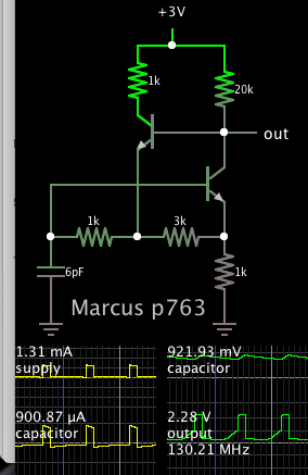
Multivibrator, frequency depends on capacitor value. 6pF yields 130 MHz.
Output transition is a few volts. Draws about 1mA from 3V supply.
Modified from initial schematic found at link below. (Caption says 'Marcus p763').
www.4qdtec.com/mvibs.html

As far as I know, RC oscillators have the worst phase noise, don't they?
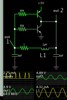
Sorry, I wasn't certain as to what waveform you want. This sine wave oscillator has a resonant current loop based on two capacitors and one inductor. They carry several mA as oscillations build. The power supply only needs to provide tiny average current.

If you reduce value of the bias resistors, it increases power in the resonating loop.
The 1 ohm resistor is unecessary.
So, you say Cprobe changes from 6pF to 18pF. That means the maximum/minimum C ratio is =18/6=3.
The LC oscillators regularly have a square root function dependence on L or C values, and sqrt(3)=1.73.
Your desired maximum frequency is 90MHz, the minimum should be 54MHz, the ratio is =90/54=1.66.
This means the practical desired ratio is pretty close to the theoretical one, the absolute maximum limit.
I don't say it is impossible, but it is hard I think to build a Colpitts/Hartley or any voltage divider based oscillator. I think you should go forward with more relieved specifications or with a structure like Meissner (or Armstrong) oscillator, where there is no frequency dependent feedback divider.
BTW I have no idea how questionable to drive an FPGA with almost 100MHz. Sounds challenging.
Now that look interesting, I'll try that circuit, looks like it can be implemented with FPGA, without any transistors.
Right now I'm using a comparator with LVDS output to convert sine wave to square, works just fine but consumes too much power.
Unfortunalely, I don't have access to any core materials, suitable for making RF transformers.
efficient Power topologies 相关文章:
