Is there possibility to force a filter topology in DA_LClowpassMatch in ADS?
Hello
Give me some more infos
What topology exactly do you want?
Source and load impedance?
Some specs?
I want typical PI filter: https://qph.fs.quoracdn.net/main-qim...3046e8c75.webp . The load impedance is 10 + 10j, and the source impedance is any - it will be matched to previous step of design.
You just want matching on one frequency? Which frequency?
If no, you need a frequency-dependent load.
Yes, i want to match to only one frequency, with pi filter.
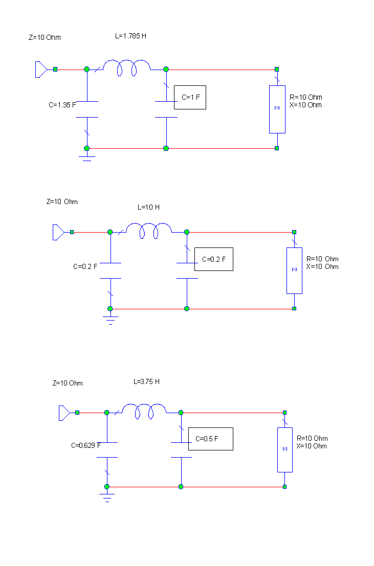
I have something like this, but i do not want to L2 here.
I dont know the tool "DA_LClowpassMatch" in ADS. But this is a classic textbook example. For only one frequency easy to solve using the Smithchart (graphical method)
With 3 elements in the matching network, you have a degree of freedom. You can choose an element.
In my example, this is the framed C. The matching frequency is ω≈1

Frequency? Load?
You give us only partial information.
@niki, and what with impedance in other side?
Maybe i will describe what i want to do to better understanding.
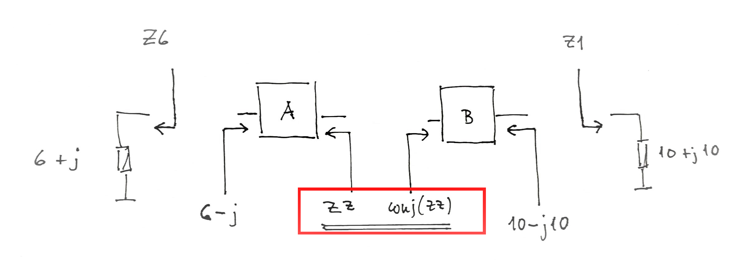
I have 2 matching blocks, A and B. I know impedances: Z1, Z2, Z5 Z6. So at this moment Z3 and Z4 are not important. Now importat is to make a pi filter with some f-cut in B block to have Z2 at the output (conjugate Z1). So if the filter will be ready, there will be some impedance Z3 - in that case, the Z4 will be conjugate Z3. Z4 will we easy to provide by A block (this is L-network)

I don't know a way to enforce pi structure in ADS filter synthesis.
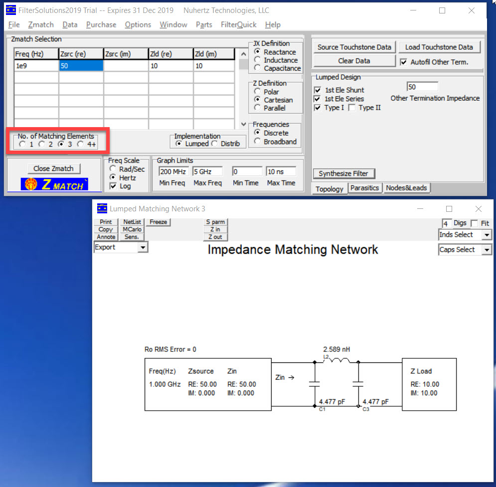
In Nuhertz you can select the number of elements, so you can enforce pi filter even if 2 element L structure is sufficient for matching.

Am I getting this right?
Z1 is the load impedance, which will be connected to the right side of B
Z2 is the input impedance of B (right side) and should be conjugate(Z1)
For synthesizing block B this is not enough information! You need the impedance, which is connected on the left side of B.
ADS Filter Design Guide does not accept complex load or source impedances. Therefore you should use a closer real impedance-for instance 10 Ohm-then place a simple matching circuit after.
If you set the filter's degree as 3 and select the first element as parallel in filter design guide control window, the first element will be a capacitor.A simple capacitor with a reactance of 10 Ohm @ desired frequency in series will shift the output impedance to 10-j*10 Ohm ( complex conjugate ) so the filter will deliver the max. power to the load.
Here is an example for clarification:
Known are: Z1 and Z6

The impedance ZZ can be chosen arbitrarily (must have an ohmic component).
Otherwise there are endless possibilities.
@BigBoss - is there possibility to set frequency in Filter guide? I mean matching frequency, not cutoff.
@niki - yes, you right. This is what i want to do, but maybe i described wrong :D
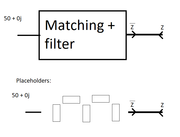
I was thinking about it, and there are not 2 blocks nesescary. 1 block which is filter and matching network is ok. ADS has this block, but there is no possibility to set matching frequency.
Give us some concrete values of your specifications. I can play with various tools. From very simple to very powerful.

Z = 16.6 + 15.1j, fcut = 500MHz (low pass), fmatch = 433.92MHz .
Very important: The constant load impedance only makes sense for one single frequency.
For a matching circuit and/or a filter circuit, the load must be known broadband (or a resistor).
Do you have an equivalent circuit for the load?
Questions about the filter specification : passband? stopband?
What is the specification in the range from 433 MHz to 500 MHz?
Filters have only cut-off frequency definition,that's it..The Input/Output Impedances are constant( already defined ) along filter specification frequency..
@BigBoss, could You extend?
There is no such definition as Matching Frequency in Filters.. Because Filters are not matching circuits.
OK, If Input and Output Impedances are properly selected, the Filter may act as a kind of matching circuit but this is not his mission.
Doubly terminated with complex impedances fiters may be designed but ADS does not inhibit to design such filters.Input and Ouput Impedances must be real in Filter Design Guide.
Along the filter bandwidth ( low-pass, bandpass whatever is ) the Input and Output Impedances are real and defined in design guide then beyond they change.
@BigBoss thanks for answer. So maybe you have suggestions what tools in ADS may be helpful to design it?
For example, if i will put the filter elements, and after that, i will make matching to 50ohm - it will be very bad?
