Input impedance of ideal passive mixer
I am trying to find the impedance of the mixer attached and later I need to do it for differential RF.
After reading https://designers-guide.org/forum/Ya...=1240334878/15, I understood that I cannot use port for RF input as port impedance(series resistance inside port) will affect the impedance measurement (ZM1 of PSP analysis). Hence I need to inject small signal voltage(Vinj) and measure current(iprobe) with PSS/PAC analysis and evaluate the "mag(v("/Vinj" ?result "pac"))/mag(i("/IPRB0/PLUS" ?result "pac"))" in calculator to find input impedance.
Complete setup :

- ideal switch with on res = 1 Ohm and Off res = 1T Ohms
- load resistance 1k Ohms.
Lo port :

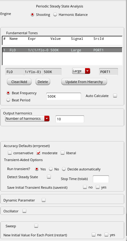
Flo= 500K Hz
tr =tf =1fs
Duty cycle = 50%
Vlo= 1.65
Small signal voltage (Vinj) :

Analysis setup for PSS:
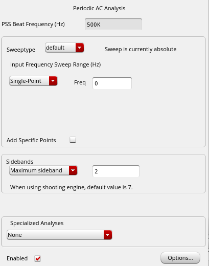
Analysis setup for PAC:
Result plot:
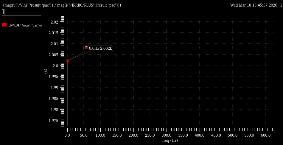
I get 2.002K Ohms as input impedance where as I expect it to be 1.001K Ohms (if not please correct me).
Is this simulation setup correct ? Why it is being scaled by a factor of 2 ?
If any information missing, let me know
My guess:
The mixer W0 is of the switching/sampling type, which means that the switch in W0 is operated at the LO frequency with a 50% duty cycle.
This means that the current is only 50% of what it would be if the switch was permanently closed.
The input impedance will be twice the value of R3.
Thanks for the reply...
For Duty cycle of 50%:
When switch is open, no current flow, Ioff =0
When switch is closed, Ion = 1V/1KOhms = 1mA
But average: Iavg= (Ion + Ioff )/2 = 0.5mA
So Zin = Vinj/Iavg results in 2K Ohms.
I tried changing the Duty cycle to 25% and I see Zin = 4K Ohms
Please correct me if i have understood it wrong...
I have one more query :
Previously I am doing fixed LO frequency(Flo=Frf = 500K) and corresponding Beat frequency(500K) to get impedance at Fundamental LO frequencies (image: Result plot )
But I want to simulate the input impedance for Flo= Frf (Direct Down conversion) in the range of few KHz to few MHz. Can any one suggest me how to setup the PSS analysis for LO sweep and Beat frequency for the same.I need Impedance in Y axis and LO Freq sweep in x-axis.
Thanks in advance
- Output Impedance Of a Triple cascode
- How to make image impedance equal
- Input and output impedance matching in Distributed amplifier
- Characteristic impedance of combination of CPWG and stripline on inner layers
- Problem of impedance matching of Gilbert cell mixer
- Input impedance of transmission lines connected in cascade